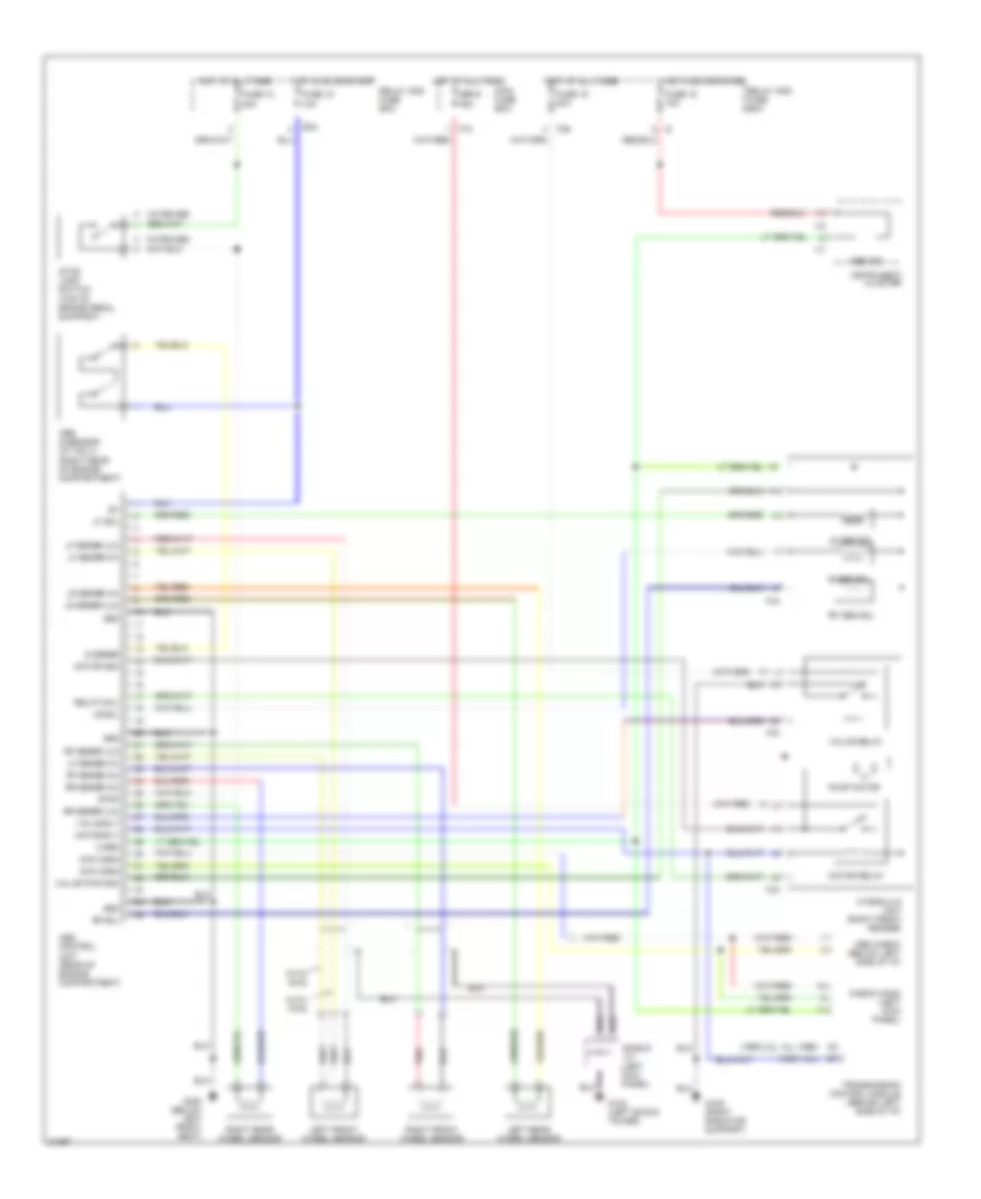
ANTI-LOCK BRAKES
Anti-lock Brake Wiring Diagrams for Subaru Impreza Brighton 1996
List of elements for Anti-lock Brake Wiring Diagrams for Subaru Impreza Brighton 1996:
- (1995 1.8l)
- (1995 2.2l, all 1996)
- (top of brake pedal support)
- (w/cruise)
- 13
- Abs check (below left side of i/p)
- Abs control unit (rear of engine compartment)
- Abs g sensor (mt only) (right rear of engine compartment)
- Abs ind
- B34
- Check conn (left kick panel)
- Chk conn
- F18
- F36
- F43
- Fuse 12 20a
- Fuse 15 10a
- Fuse 18 10a
- Fuse 19 20a
- G sensr
- G102 (left shock tower)
- G109 (right radiator support)
- G300 (below left front seat)
- Gnd
- Hot at all times
- Hot in on or start
- Hydraulic unit (right front fender)
- I17
- I18
- Instrument cluster
- Left front wheel sensor
- Left rear wheel sensor
- Lf abs sol
- Lf sensr (hi)
- Lf sensr (lo)
- Lf sol
- Lr sensr (hi)
- Lr sensr (lo)
- Lr sol
- Main fuse box
- Motor mon
- Motor relay
- Motor rly
- Pnk
- Pump motor
- R abs sol
- Relay and fuse box
- Relay coil
- Rf abs sol
- Rf sensr (hi)
- Rf sensr (lo)
- Rf sol
- Right front wheel sensor
- Right rear wheel sensor
- Rr sensr (hi)
- Rr sensr (lo)
- Sbf-6 45a
- Shield j/c (left kick panel)
- Stop
- Stop lamp switch
- Transmission control module (behind left side of i/p)
- Valve pwr mon
- Valve relay
- Valve rly
- Warn
- With awd
- With fwd
 English