ANTI-LOCK BRAKES
Anti-lock Brakes Wiring Diagram for Suzuki Aerio SX 2003
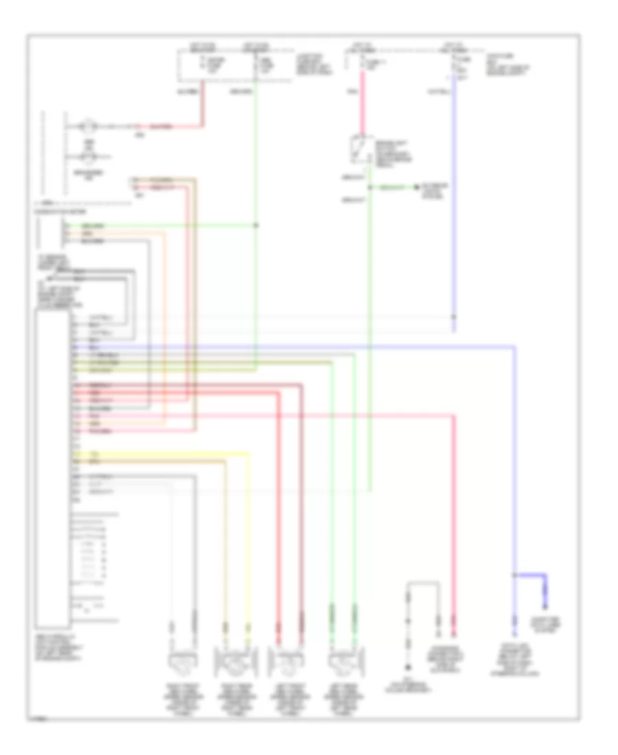
List of elements for Anti-lock Brakes Wiring Diagram for Suzuki Aerio SX 2003:
- "g" sensor (under left front seat)
- Abs fuse 10a
- Abs hydraulic unit/control module assembly (on left rear of engine compt)
- Abs ind
- Brake/ebd ind
- Brakelight switch (on bracket, above brake pedal)
- Combination meter
- Computer data lines system
- Cpu
- Data link connector (below left side of dash, right of steering column)
- Diagnosis connector 2 (behind right side of glove box)
- E17
- Exterior lights system
- Fuse 11 15a
- Fuse 60a
- G11 (on steering column bracket)
- G20
- G21
- G7 (at left side of engine compt, near washer fluid reservoir)
- Hot at all times
- Hot in on or start
- Junction/ fuse box (behind left side of dash)
- Left front abs wheel speed sensor (inside of left front wheel)
- Left rear abs wheel speed sensor (inside of left rear wheel)
- Main fuse box (on left side of engine compt)
- Meter fuse 10a
- Pnk
- Red
- Right front abs wheel speed sensor (inside of right front wheel)
- Right rear abs wheel speed sensor (inside of right rear wheel)
 English