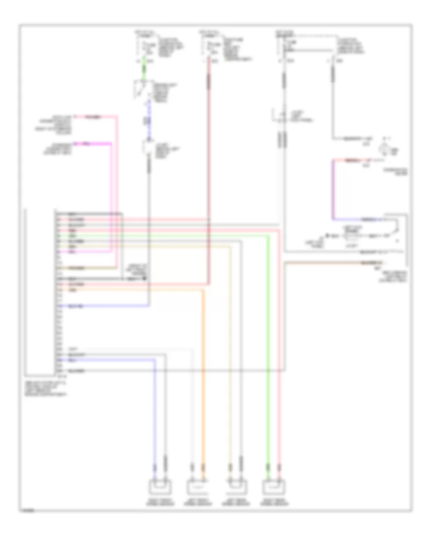
ANTI-LOCK BRAKES
Anti-lock Brake Wiring Diagrams for Suzuki Esteem GL 2002
List of elements for Anti-lock Brake Wiring Diagrams for Suzuki Esteem GL 2002:
- (front of left front fender) g2
- (left kick panel)
- Abs actuator unit & control module (left rear of engine compartment)
- Abs ind
- Abs warning lamp relay (on relay box)
- Brakelight switch (above brake pedal)
- Combination meter
- Data link connector (dlc) (partial) (right of steering column)
- Diagnosis connector 2 (on relay box)
- E116
- E16
- E18
- E67
- E70
- Fuse 20a
- Fuse 60a
- G18
- G19
- G28
- G7 (left kick panel)
- Hot at all times
- Hot in on or start
- J/c e07 (behind left side of dash)
- J/c e71
- J/c e71 (left kick panel)
- Junction fuse block (behind left side of dash)
- Left front speed sensor
- Left rear speed sensor
- Main fuse box (on left side of engine compartment)
- Red
- Right front speed sensor
- Right rear speed sensor
 English