ANTI-LOCK BRAKES
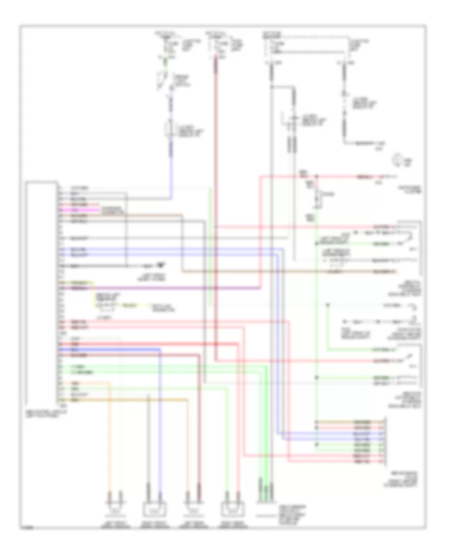
Anti-lock Brake Wiring Diagrams for Suzuki Esteem GLX+ 1997
List of elements for Anti-lock Brake Wiring Diagrams for Suzuki Esteem GLX+ 1997:
- (behind left side of i/p)
- (left front of engine compt)
- (left front shock tower)
- (left rear of engine compt)
- Abs control module (left kick panel)
- Abs fail- safe relay (in engine room relay box)
- Abs g sensor (4wd only) (below front of center console)
- Abs ind
- Abs pump motor relay (in engine room relay box)
- Abs solenoid valve (front center of engine compt)
- Brake light switch
- Data link connector
- Diagnosis connector
- Diode
- E16
- E18
- E22
- E23
- E70
- Fuse 20a
- Fuse 60a
- G100
- G100 (left front of engine compt)
- G102
- G18
- G19
- G28
- Hot at all times
- Hot in on or start
- Instrument cluster
- J/c (e07)
- J/c (e07) (behind left side of i/p)
- J/c (e71)
- J/c (g26) (behind left side of i/p)
- Junction fuse box
- Left front speed sensor
- Left rear speed sensor
- Main fuse box
- Pump motor (front center of engine compt)
- Red
- Right front speed sensor
- Right rear speed sensor
 English