ANTI-LOCK BRAKES
Anti-lock Brakes Wiring Diagram for Suzuki Kizashi Sport GTS 2011
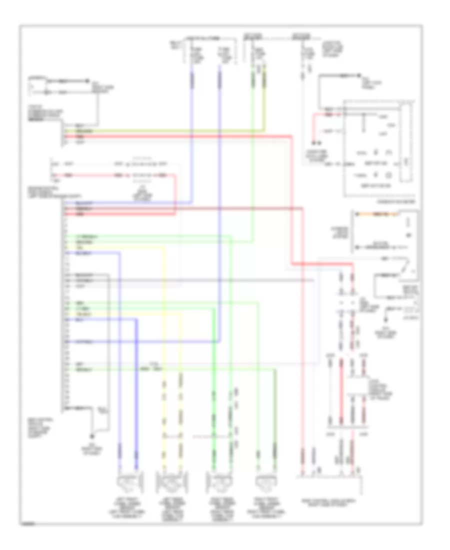
List of elements for Anti-lock Brakes Wiring Diagram for Suzuki Kizashi Sport GTS 2011:
- (top of steering column) steering angle sensor
- 2wd
- 4wd
- 4wd control module (right side of trunk)
- Abs mot fuse 40a
- Abs sol fuse 25a
- Body control module (bcm) (right side of dash)
- Can
- Combination meter
- Computer data lines system
- Cpu
- E01
- E05
- E323
- E382
- E387
- Engine control module (ecm) (left side of engine compt)
- Esp active ind
- Esp control module (right side of engine compt)
- Esp fuse 10a
- Esp off ind
- Esp off switch
- G10 (right end of dash)
- G12 (left kick panel)
- G14 (right side of dash)
- G271
- G334
- G341
- High
- Hot at all times
- Hot in on or start
- Interior lights system
- J/c e346 (left side of dash)
- J/c g306 (left side of dash)
- J/c g312
- Junction block (j/b) (left side of dash)
- L03
- L347
- L371
- L422
- L424
- Left front wheel speed sensor (left front wheel hub assembly)
- Left rear wheel speed sensor (left rear wheel hub assembly)
- Low
- Mtr fuse 7.5a
- Red
- Relay box 1
- Right front wheel speed sensor (right front wheel hub assembly)
- Right rear wheel speed sensor (right rear wheel hub assembly)
 English