ANTI-LOCK BRAKES
Anti-lock Brake Wiring Diagrams for Suzuki Sidekick JLX 1995
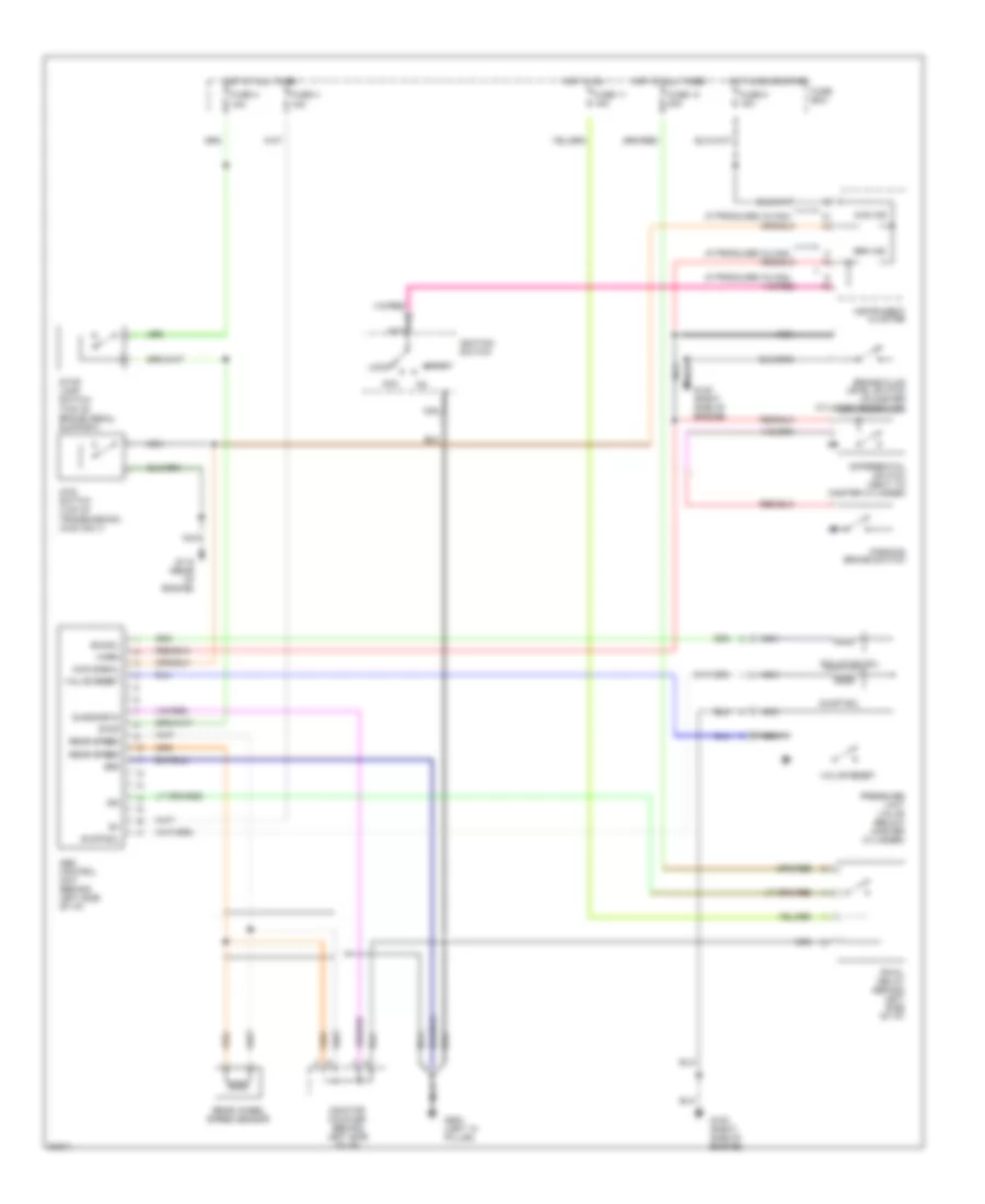
List of elements for Anti-lock Brake Wiring Diagrams for Suzuki Sidekick JLX 1995:
- (if produced in can)
- (top of brake pedal support)
- (top of transmission) (4wd only)
- 13
- 4wd ind
- 4wd signal
- 4wd switch
- Abs control unit (behind left side of i/p)
- Acc
- Brake fluid level switch (in master cylinder reservoir)
- Brk ind
- Diagnostic
- Differential switch (next to master cylinder)
- Dump sol
- Fuse 11 15a
- Fuse 13 20a
- Fuse 3 15a
- Fuse 4 15a
- Fuse 8 15a
- Fuse box
- G115 (rear of engine)
- G120 (right side of engine)
- G900 (left "a" pillar)
- Gnd
- Hot at all times
- Hot in on
- Hot in on or start
- Ign
- Ignition switch
- Instrument cluster
- Iso sol
- Isolation sol
- Lock
- Monitor coupler (behind left side of i/p)
- Nca
- Parking brake switch
- Pressure limit valve (below master cylinder)
- Rear speed
- Rear wheel speed sensor
- Rwal relay (behind left side of i/p)
- Start
- Stop
- Stop lamp switch
- Valve reset
- Warn
 English