ANTI-LOCK BRAKES
Anti-lock Brakes Wiring Diagram, with ESP for Suzuki SX4 Sport 2008

List of elements for Anti-lock Brakes Wiring Diagram, with ESP for Suzuki SX4 Sport 2008:
- (in steering column assembly) steering angle sensor
- Abs fuse 10a
- Abs mot fuse 40a
- Abs sol fuse 30a
- Body control module (bcm) (left side of dash)
- Brake light switch (top of brake pedal assembly)
- Can
- Combination meter
- Computer data lines system
- Dome fuse 15a
- E01
- E323
- E325
- Engine control module (ecm) (at side of battery)
- Esp active ind (if equipped)
- Esp control module (right rear of engine compartment)
- Esp off ind (if equipped)
- Esp off switch
- Esp system ind (if equipped)
- Exterior lights system
- G05
- G11 (behind right kick panel)
- G13 (behind left kick panel)
- G16 (under front passenger's seat)
- G17 (under driver's seat)
- G271
- G272
- G8 (at right front strut tower)
- High
- Hot at all times
- Hot in on or start
- Ig 1 sig fuse 10a
- Individual circuit fuse box 1
- Interior lights system
- J/c 309
- J/c g241
- J/c g308
- J/c g309
- J/c g311
- J/c l348
- Junction block assembly (left side of dash)
- L315
- Led output driver stepper motor &
- Left front wheel speed sensor (at left front wheel hub assembly)
- Left rear wheel speed sensor (at left rear wheel hub assembly)
- Low
- Micro controller
- Mtr fuse 10a
- Red
- Right front wheel speed sensor (at right front wheel hub assembly)
- Right rear wheel speed sensor (at right rear wheel hub assembly)
- Stop fuse 15a
- Yaw/g sensor (under center console, below parking brake handle)
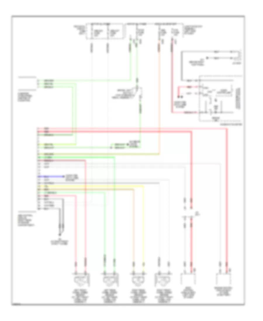
Anti-lock Brakes Wiring Diagram, without ESP for Suzuki SX4 Sport 2008
List of elements for Anti-lock Brakes Wiring Diagram, without ESP for Suzuki SX4 Sport 2008:
- Abs control module (right rear of engine compartment)
- Abs fuse 10a
- Abs ind
- Abs mot fuse 40a
- Abs sol fuse 30a
- Body control module (bcm) (left side of dash)
- Brake ind
- Brake light switch (top of brake pedal assembly)
- Can
- Combination meter
- Computer data lines system
- E01
- E323
- E325
- Engine control module (ecm) (at side of battery)
- Exterior lights system
- G sensor (if equipped) (center of floor pan)
- G05
- G11 (behind right kick panel)
- G271
- G8 (at right front strut tower)
- High
- Hot at all times
- Hot in on or start
- Individual circuit fuse box 1
- J/c g309
- J/c g311
- Junction block assembly (left side of dash)
- L315
- Led output driver stepper motor &
- Left front wheel speed sensor (at left front wheel hub assembly)
- Left rear wheel speed sensor (at left rear wheel hub assembly)
- Low
- Micro controller
- Mtr fuse 10a
- Red
- Right front wheel speed sensor (at right front wheel hub assembly)
- Right rear wheel speed sensor (at right rear wheel hub assembly)
- Stop fuse 15a