ANTI-LOCK BRAKES
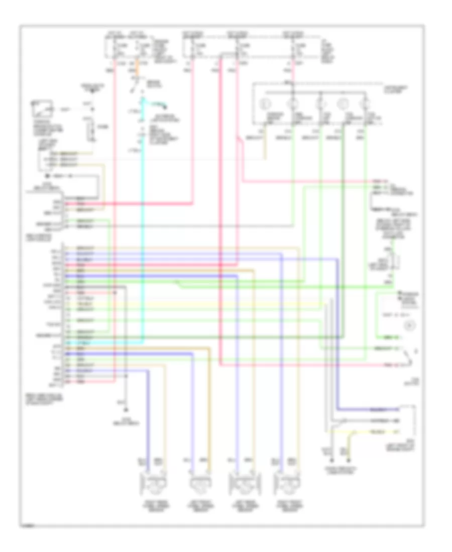
Anti-lock Brakes Wiring Diagram for Suzuki Verona LX 2005
List of elements for Anti-lock Brakes Wiring Diagram for Suzuki Verona LX 2005:
- (below left side of dash, right of steering column) data link connector
- (left end of dash)
- (left end of dash) s201
- A13
- A14
- A16
- Abs warning ind
- Abs warning lamp module
- Abs wlp
- Abs/ebd wlp
- B14
- Bat (+)
- Bat (-)
- Brake switch
- Bws
- C102
- C105
- C15
- C201
- C202
- Can hi
- Can low
- Computer data lines system
- Diode
- Ebcm (abs module) (left rear corner of eng compt)
- Ebd wlp
- Ecm (left front of engine compt)
- Engine fuse block (left front of eng compt)
- Exterior lights system
- Fl (+)
- Fl (-)
- Fr (+)
- Fr (-)
- Fuse 10a
- Fuse 20a
- Fuse 60a
- G105 (below ebcm)
- Gnd
- Headlights system
- Hot at all times
- Hot in run or start
- I/p fuse block (left end of dash)
- Ign1
- Instrument cluster
- Interior lights system
- Kwp 2000
- Left front wheel speed sensor
- Left rear wheel speed sensor
- Oil feeding connector
- Parking brake ind
- Parking brake switch (under center console)
- Pnk
- Red
- Right front wheel speed sensor
- Right rear wheel speed sensor
- Rl+
- Rl-
- Rr+
- Rr-
- S201
- S301 (behind right side of instrument cluster)
- Stp
- Tcs active ind
- Tcs off ind
- Tcs sw
- Tcs switch
- Tcs warning ind
 Русский