ANTI-LOCK BRAKES
Anti-lock Brake Wiring Diagrams for Suzuki X-90 1996
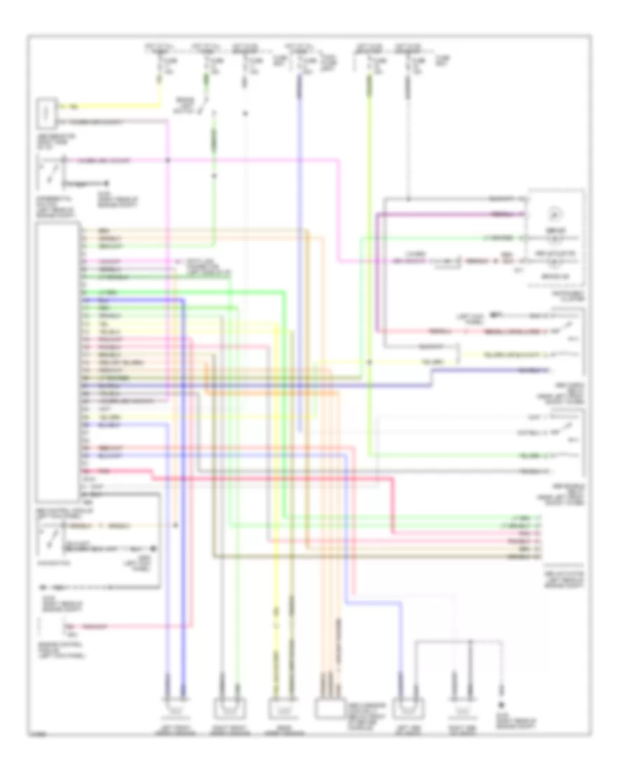
List of elements for Anti-lock Brake Wiring Diagrams for Suzuki X-90 1996:
- (4at)
- (exc. 4at)
- (left kick panel)
- 4wd switch
- Abs active ind
- Abs actuator (left rear of engine compt)
- Abs check relay (near left front shock tower)
- Abs control module (left kick panel)
- Abs enable relay (near left front shock tower)
- Abs g sensor (4wd only) (below front of center console)
- Abs ind
- Abs resistor (right side of i/p)
- Brake ind
- Brake light switch
- Data link connector (left side of i/p)
- Differential switch (left rear of engine compt)
- E124
- E34
- E65
- Engine control module (left kick panel)
- Fuse 15a
- Fuse a 50a
- Fuse box
- G105 (right rear of engine compt)
- G11
- G200
- G200 (left kick panel)
- Hot at all times
- Hot in on or start
- Instrument cluster
- Left abs solenoid
- Left front speed sensor
- Main fuse box
- Pnk
- Rear speed sensor
- Red/
- Right abs solenoid
- Right front speed sensor
 English