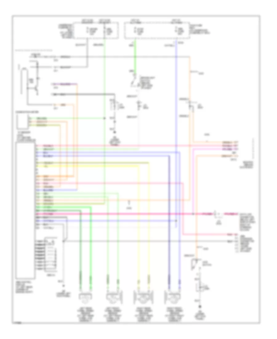
ANTI-LOCK BRAKES
Anti-lock Brakes Wiring Diagram for Suzuki XL-7 2003
List of elements for Anti-lock Brakes Wiring Diagram for Suzuki XL-7 2003:
- 4wd
- 4wd ind
- 4wd switch
- Abs control module (at left rear corner of engine compt)
- Abs diagnosis connector (behind lower left side of dash)
- Abs fuse 10a
- Abs fuse 60a
- Abs hu
- Abs ind
- Brakelight switch (behind left side of dash)
- C51-2
- Combination meter
- Cpu
- Data link connector (below left side of dash, right of steering column)
- E120
- E61
- Ecm/pcm (behind glove box)
- G10
- G11
- G9 (under left kick panel)
- Hot at all times
- Hot in on or start
- J/c (c69)
- J/c (e42)
- J/c (e43)
- J/c (g16)
- J/c (g29)
- Left front wheel speed sensor (at left front wheel hub assembly)
- Left rear wheel speed sensor (at left rear wheel hub assembly)
- Main fuse box (in underhood fuse/relay box)
- Meter fuse 10a
- Nca
- Pnk
- Right front wheel speed sensor (at right front wheel hub assembly)
- Right rear wheel speed sensor (at right rear wheel hub assembly)
- Stop fuse 15a
- Underdash fuse/relay box (at lower left side of dash)
- ``g" sensor (4wd) (at center floor console)
 English