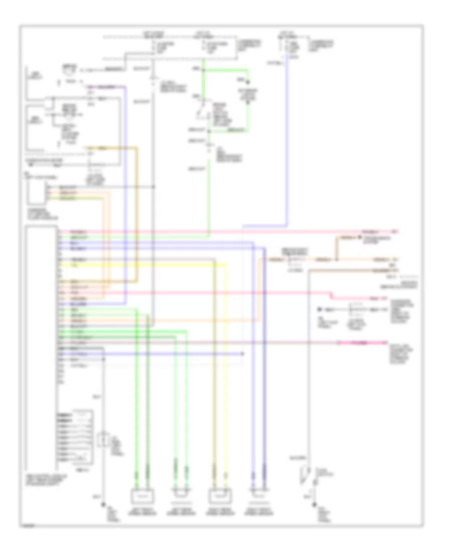
ANTI-LOCK BRAKES
Anti-lock Brake Wiring Diagrams for Suzuki XL-7 Touring 2002
List of elements for Anti-lock Brake Wiring Diagrams for Suzuki XL-7 Touring 2002:
- (behind right side of dash)
- 4wd switch
- Abs circuit
- Abs control module (left rear corner of engine compt)
- Abs fuse 60a
- Abs hu
- Abs ind
- Brake- light switch (behind left side of dash)
- Brake/ ebd ind
- C51-3
- Combination meter
- Data link connector (right of steering column)
- Diagnosis connector (abs) (right of steering column)
- E124
- E61
- Ebd circuit
- Ecm/pcm (behind glove box)
- Exterior lights system
- G-sensor (at center floor console)
- G10 (right kick panel)
- G11
- G12
- G9 (left kick panel)
- Hot at all times
- Hot in run or start
- Ig meter fuse 20a
- Instru- ment cluster system
- J/c (e19) (left kick panel)
- J/c (e41) (behind right side of dash)
- J/c (e42)
- J/c (e42) (behind right side of dash)
- J/c (e46) (left kick panel)
- J/c (g15) (left side of dash)
- Left front speed sensor
- Left rear speed sensor
- Nca
- Pnk
- Right front speed sensor
- Right rear speed sensor
- Stop horn fuse 15a
- Transmission system
- Underdash fuse/relay box
- Underhood fuse/relay box
 English