ANTI-LOCK BRAKES
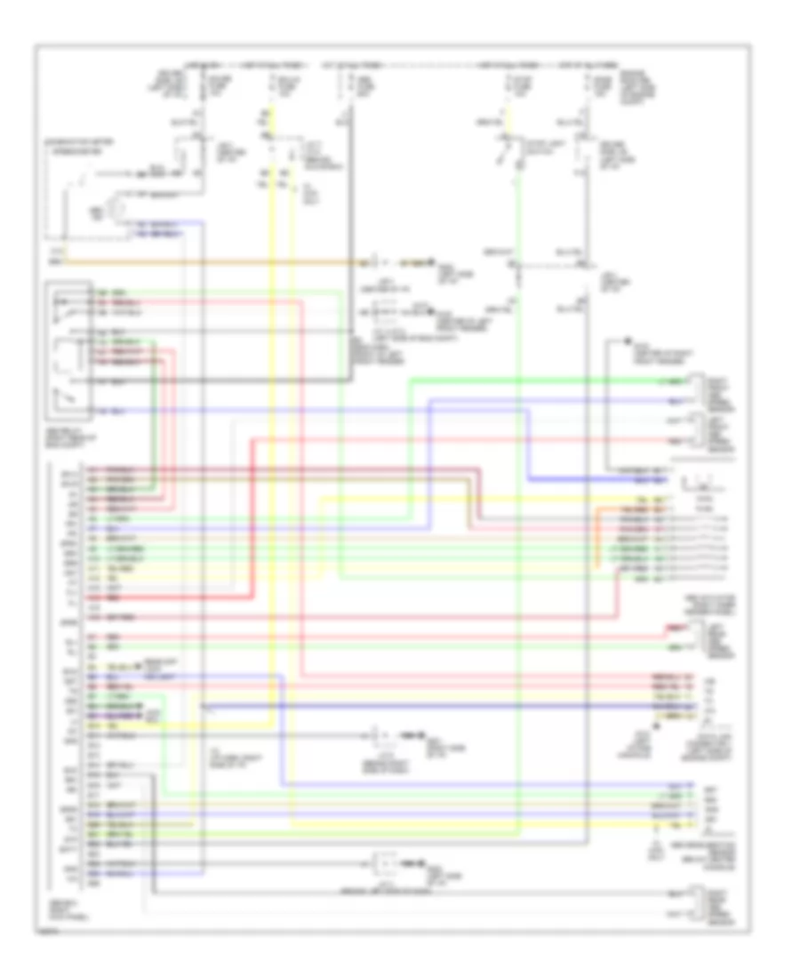
Anti-lock Brake Wiring Diagrams for Toyota 4Runner SR5 1996
List of elements for Anti-lock Brake Wiring Diagrams for Toyota 4Runner SR5 1996:
- 4wd ecu
- A10
- A11
- A12
- A13
- A14
- A15
- A16
- Abs actuator (right inner fender panel)
- Abs deceleration sensor (below center console)
- Abs ecu (right kick panel)
- Abs fuse 60a
- Abs ind
- Abs relay (right rear of eng compt)
- Ast
- B10
- B11
- B12
- B13
- B14
- B15
- B16
- B17
- B18
- B19
- B20
- B21
- B22
- B23
- B24
- B25
- B26
- Batt
- C12
- Combination meter
- Data link connector 1 (left side of engine compt)
- Dome fuse 15a
- Driver side j/b (left side of i/p)
- E3 (eng harn, front of left front fender)
- Ecu-ig fuse 10a
- Engine room r/b (left side of engine compt)
- Exi
- Exi2
- Exo
- F12
- Fl+
- Fl-
- Fr+
- Fr-
- G102 (center of left front fender)
- G103 (center of right front fender)
- G131 (left intake manifold)
- G201 (right side of i/p)
- G202 (left side of i/p)
- Gauge fuse 10a
- Ggnd
- Gnd
- Gs1
- Gs2
- Gst
- Hot at all times
- Hot in on
- I12 (i/p harn, right side of i/p)
- Ig1
- J/b 3 (center of i/p)
- J/c 1/j/c 2 (left side of eng compt)
- J/c 4 (behind left side of dash)
- J/c 7/ j/c 8 (behind glove box)
- J/c 9 (behind right side of dash)
- J12
- Left front abs speed sensor
- Left rear abs speed sensor
- Nca
- Rear diff lock ind light
- Red
- Right front abs speed sensor
- Right rear abs speed sensor
- Rl+
- Rl-
- Rr+
- Rr-
- Sflh
- Sflr
- Sfrh
- Sfrr
- Speedometer
- Srh
- Srr
- Stop fuse 10a
- Stop light switch
- Stp
- W/ 4wd only
 English