ANTI-LOCK BRAKES
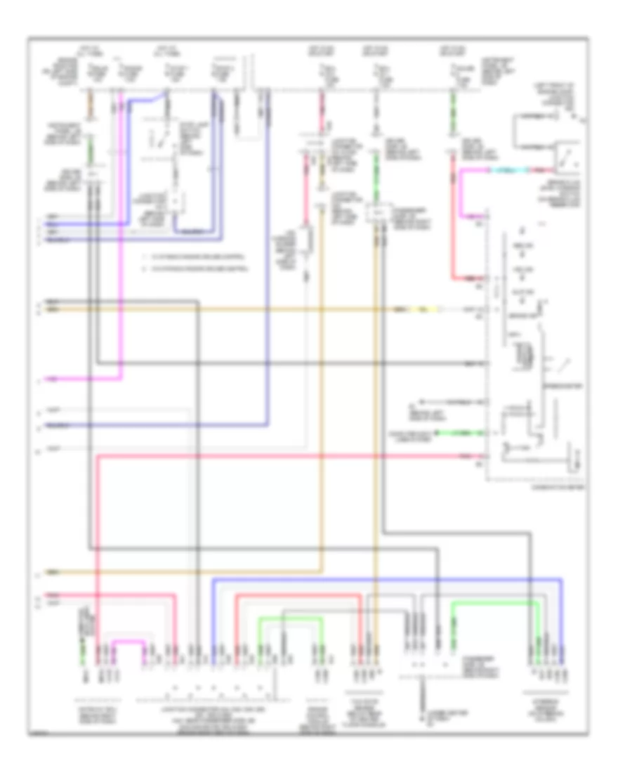
Anti-lock Brakes Wiring Diagram, with VSC (1 of 2) for Toyota Avalon XL 2007

List of elements for Anti-lock Brakes Wiring Diagram, with VSC (1 of 2) for Toyota Avalon XL 2007:
- +bs
- A41
- A6 (at right end of dash)
- Abs/ vsc 1 fuse 50a
- Abs/ vsc 2 fuse 30a
- Brk relay (w/ dynamic radar cruise control)
- C14
- Canh
- Canl
- D/g
- D13
- D46
- Data link connector 3 (at lower left side of dash)
- Ecu ig 2 fuse 10a
- Engine room r/b (on left side of engine compt)
- F19
- Fl+
- Fl-
- Fr+
- Fr-
- Gnd1
- Gnd2
- Headlamp leveling ecu (behind left side of dash)
- Hot at all times
- Hot in on or start
- Ig1
- Instrument panel j/b (behind left side of dash)
- Junction connector a41 & d46 (behind left side of dash)
- Junction connector a42 (behind left side of dash)
- Junction connector a54 (right front of engine compt)
- Left front speed sensor (mounted on left front wheel hub assembly)
- Left rear speed sensor (mounted on left rear wheel hub assembly)
- Mrf
- Nca
- Parking brake switch (on parking brake pedal assembly)
- Passenger side j/b (behind right side of dash)
- Pkb
- Pnk
- Red
- Right front speed sensor (mounted on right front wheel hub assembly)
- Right rear speed sensor (mounted on right rear wheel hub assembly)
- Rl+
- Rl-
- Rlo
- Rr+
- Rr-
- Rro
- Sil
- Skid control ecu w/ actuator (at right side of engine compt)
- Sp1
- Spdl
- Spdr
- Stp1
- Stp2
- Stpo
- Vsc 1 relay
- Vsc 2 relay
- W/ dynamic radar cruise control
- Wfse
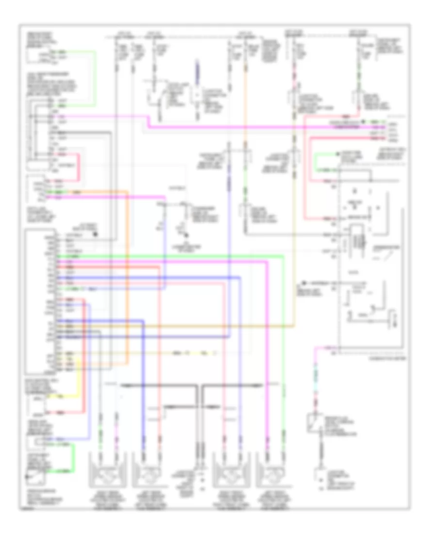
Anti-lock Brakes Wiring Diagram, with VSC (2 of 2) for Toyota Avalon XL 2007
List of elements for Anti-lock Brakes Wiring Diagram, with VSC (2 of 2) for Toyota Avalon XL 2007:
- (left front of engine comp) junction connector a52
- (under center of dash) d2
- A44
- Abs ind
- B10
- B11
- B16
- Bat
- Brake fluid level warning switch (on brake fluid reservoir)
- Brake ind
- Buzzer
- C13
- Ca1h
- Ca1l
- Canh
- Canl
- Combination meter
- Computer data lines system
- D10
- D20
- D41
- D46
- D48
- D49
- D50
- D51
- D52
- Driver side j/b (behind left side of dash)
- E1 (behind left side of dash)
- E14
- E28
- Ecu ig 1 fuse 7.5a
- Ecu ig 2 fuse 10a
- Ecu-b fuse 10a
- Engine control module (behind right side of dash)
- Engine room r/b (on left side of engine compt)
- Ess
- F11
- F15
- F19
- G12
- Gateway ecu (behind right side of dash)
- Gauge fuse 7.5a
- Gnd
- Hot at all times
- Hot in on or start
- I11
- Instrument panel j/b (behind left side of dash)
- Junction connector a41 & d46 (behind a41
- Junction connector a41 (behind left side of dash)
- Junction connector a42 (behind left side of dash)
- Junction connector a44, d48, d49, d50, d51, d52 & e28 (a44: near passenger side j/b) (d48,d49,d50,d51,d52 & e28: behind right end of dash)
- K15
- Left side of dash)
- Mpd1
- Mpd2
- Mpx +b
- Passenger side j/b (behind right side of dash)
- Pnk
- Power
- Radar fuse 7.5a
- Red
- Slip ind
- Speedometer
- Steering sensor (on steering column)
- Stop 1 fuse 15a
- Stop 2 fuse 7.5a
- Stop lamp switch (behind left side of dash)
- Vsc ind
- Vsc warning buzzer (behind left side of dash)
- W/ dynamic radar cruise control
- W/o dynamic radar cruise control
- Yaw rate sensor (below rear of center floor console)
Anti-lock Brakes Wiring Diagram, without VSC for Toyota Avalon XL 2007
List of elements for Anti-lock Brakes Wiring Diagram, without VSC for Toyota Avalon XL 2007:
- (a44: near passenger side j/b) (d48,d49,d50,d51,d52 & e28: behind right end of dash) junction connector a44, d50, d51, d52 & e28
- (at right end of dash) a6
- (behind right side of dash)
- (behind right side of dash) engine control module
- +bm
- +bs
- A41
- A44
- Abs ind
- Abs/ vsc 1 fuse 50a
- Abs/ vsc 2 fuse 30a
- Brake fluid level warning switch (on brake fluid reservoir)
- Brake ind
- C13
- C14
- Ca1h
- Ca1l
- Canh
- Canl
- Combination meter
- Computer data lines system
- D/g
- D10
- D13
- D2 (under center of dash)
- D41
- D46
- D50
- D51
- D52
- Data link connector 3 (at lower left side of dash)
- Driver side j/b (behind left side of dash)
- E1 (behind left side of dash)
- E28
- Ecu ig 2 fuse 10a
- Ecu-b fuse 10a
- Engine room r/b (on left side of engine compt)
- F15
- F19
- Fl+
- Fl-
- Fr+
- Fr-
- G12
- Gateway ecu
- Gauge fuse 7.5a
- Gnd1
- Gnd2
- Headlamp leveling ecu (behind left side of dash)
- Hot at all times
- Hot in on or start
- I11
- Ig1
- Instrument panel j/b (behind left side of dash)
- Junction connector a41 & d46 (behind left side of dash)
- Junction connector a41 (behind left side of dash)
- Junction connector a42 (behind left side of dash)
- Junction connector a52 (left front of engine compt)
- Junction connector a54 (right front of engine compt)
- K15
- Left front speed sensor (mounted on left front wheel hub assembly)
- Left rear speed sensor (mounted on left rear wheel hub assembly)
- Mpd1
- Mpd2
- Mpx +b
- Nca
- Parking brake switch (on parking brake pedal assembly)
- Passenger side j/b (behind right side of dash)
- Pkb
- Pnk
- Red
- Right front speed sensor (mounted on right front wheel hub assembly)
- Right rear speed sensor (mounted on right rear wheel hub assembly)
- Rl+
- Rl-
- Rlo
- Rr+
- Rr-
- Rro
- Sil
- Skid control ecu w/ actuator (at right side of engine compt)
- Sp1
- Spdl
- Spdr
- Speedometer
- Stop 1 fuse 15a
- Stop fuse 7.5a
- Stop lamp switch (behind left side of dash)
- Stp