ANTI-LOCK BRAKES
Anti-lock Brake Wiring Diagrams for Toyota Avalon XLS 1996
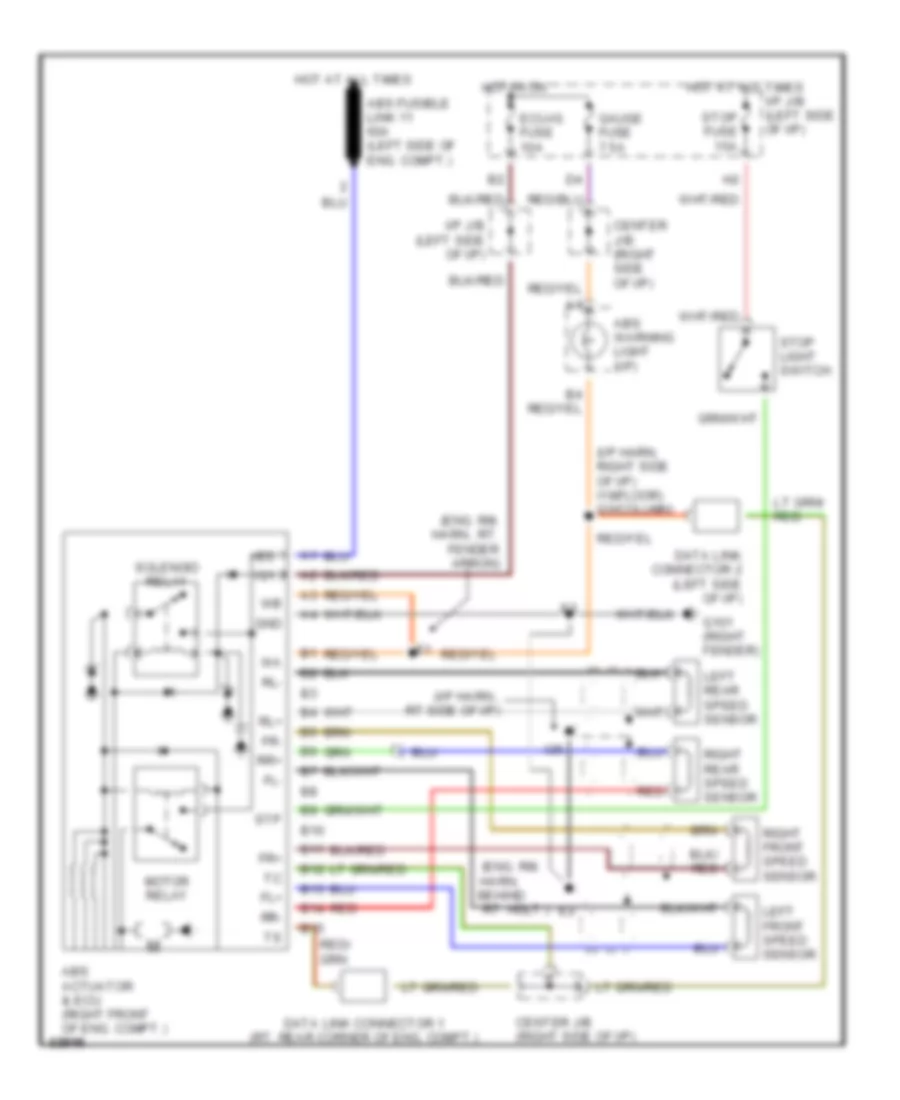
List of elements for Anti-lock Brake Wiring Diagrams for Toyota Avalon XLS 1996:
- (eng. rm.
- (eng. rm. harn., rt. fender apron)
- (i/p harn, right side of i/p) i19(floor) i20(column)
- (i/p harn., rt side of i/p)
- +bs
- Abs actuator & ecu (right front of eng. compt.)
- Abs fusible link 11 60a (left side of eng. compt.)
- Abs warning light (i/p)
- B10
- B11
- B12
- B13
- B14
- B15
- Center j/b (right side of i/p)
- Data link connector 1 (rt. rear corner of eng. compt.)
- Data link connector 2 (left side of i/p)
- Ecu-ig fuse 10a
- Fl+
- Fl-
- Fr+
- Fr-
- G101 (right fender)
- Gauge fuse 7.5a
- Gnd
- Harn, behind
- Hot at all times
- Hot in on
- I/p j/b (left side of i/p)
- I26
- Ig1
- Left front speed sensor
- Left rear speed sensor
- Motor relay
- Red
- Right front speed sensor
- Right rear speed sensor
- Rl+
- Rl-
- Rr+
- Rr-
- Rt. hdlt.)
- Solenoid relay
- Stop fuse 15a
- Stop light switch
- Stp
 English