ANTI-LOCK BRAKES
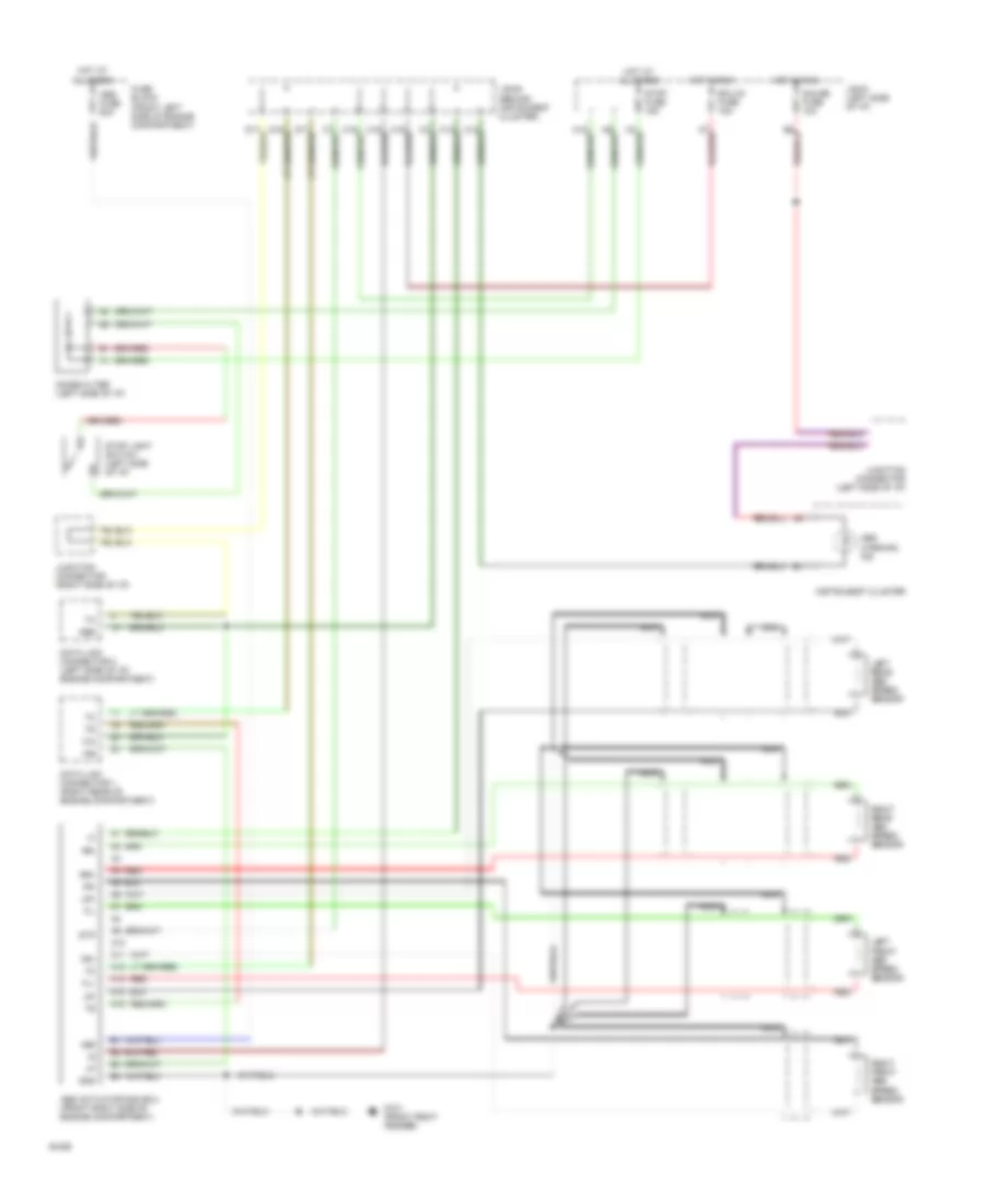
Anti-lock Brake Wiring Diagrams, TMC Made for Toyota Camry LE 1994

List of elements for Anti-lock Brake Wiring Diagrams, TMC Made for Toyota Camry LE 1994:
Anti-lock Brake Wiring Diagrams, TMM Made for Toyota Camry LE 1994
List of elements for Anti-lock Brake Wiring Diagrams, TMM Made for Toyota Camry LE 1994: