ANTI-LOCK BRAKES
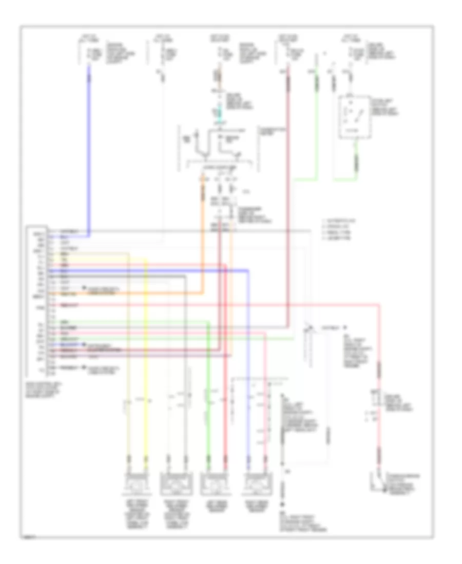
Anti-lock Brakes Wiring Diagram, Japan Production for Toyota Camry LE 2004

List of elements for Anti-lock Brakes Wiring Diagram, Japan Production for Toyota Camry LE 2004:
Anti-lock Brakes Wiring Diagram, USA Production for Toyota Camry LE 2004
List of elements for Anti-lock Brakes Wiring Diagram, USA Production for Toyota Camry LE 2004:
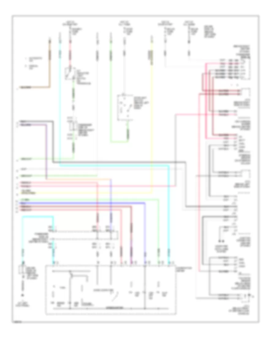
Anti-lock Brakes Wiring Diagram, with VSC (1 of 2) for Toyota Camry LE 2004
List of elements for Anti-lock Brakes Wiring Diagram, with VSC (1 of 2) for Toyota Camry LE 2004:
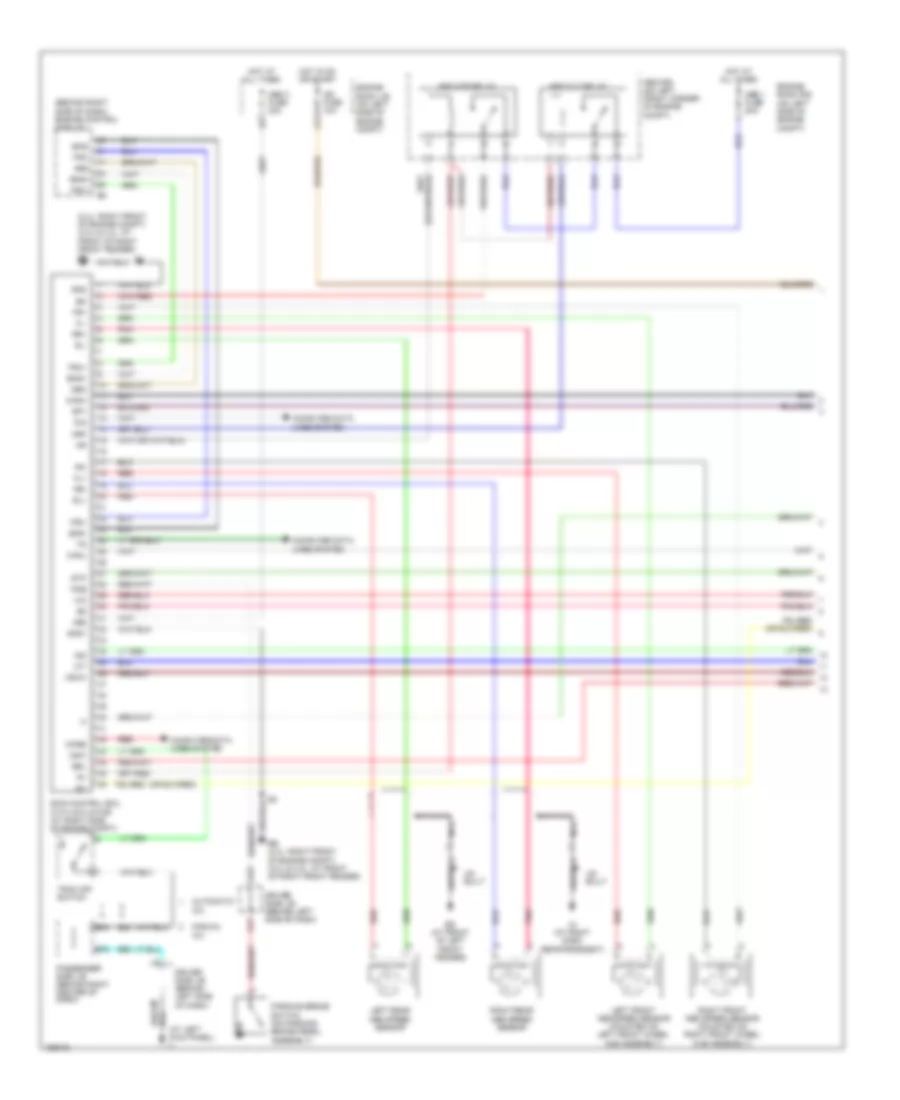
Anti-lock Brakes Wiring Diagram, with VSC (2 of 2) for Toyota Camry LE 2004
List of elements for Anti-lock Brakes Wiring Diagram, with VSC (2 of 2) for Toyota Camry LE 2004: