ANTI-LOCK BRAKES
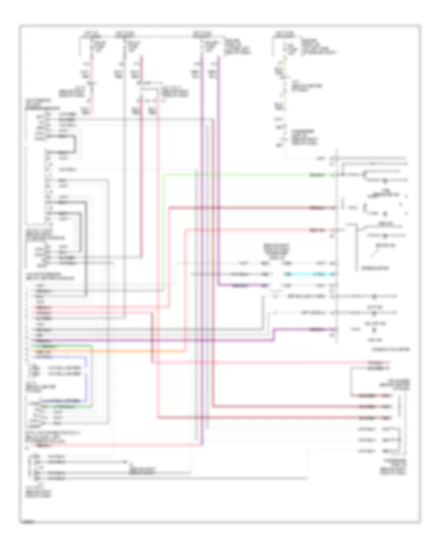
Anti-lock Brakes Wiring Diagram, with VSC (1 of 2) for Toyota Camry Solara SLE 2005

List of elements for Anti-lock Brakes Wiring Diagram, with VSC (1 of 2) for Toyota Camry Solara SLE 2005:
- (at left fender) ed
- (behind right side of dash) engine control module
- +bs
- A/t indicator light switch (on transaxle)
- Abs 1 fuse 50a
- Abs 2 fuse 25a
- Abs cut relay
- Abs mtr relay
- B120
- B52
- B62
- B90
- Brl
- C13
- C14
- Canh
- Canl
- Csw
- D/g
- Driver side j/b (lower left end of dash)
- E10
- Eb (at right fender)
- Eng+
- Eng-
- Engine room j/b (on left side of engine compt)
- Fl+
- Fl-
- Fr+
- Fr-
- Gnd1
- Gnd2
- Hot at all times
- Ig1
- Ind
- Init
- Instrument cluster system
- J/c 1 (behind center of dash)
- Left front abs speed sensor (mounted on left front wheel hub assembly)
- Left rear abs speed sensor (mounted on left rear wheel hub assembly)
- M12
- Mrf
- Neo
- Parking brake switch (on base of parking brake lever)
- Passenger side j/b (behind right side of dash)
- Pkb
- Pnk
- Pressure switch (right front of engine compt)
- Red
- Right front abs speed sensor (mounted on right front wheel hub assembly)
- Right rear abs speed sensor (mounted on left rear wheel hub assembly)
- Rl+
- Rl-
- Rr+
- Rr-
- Skid control ecu w/ actuator (right side of engine compt)
- Sp1
- Stop fuse 15a
- Stoplight switch (on bracket, above brake pedal)
- Stp
- Trac off switch
- Trc+
- Trc-
- Tsi
- Vsc r/b (left front of engine compt)
- Vscw
- Wfse
- Wtir
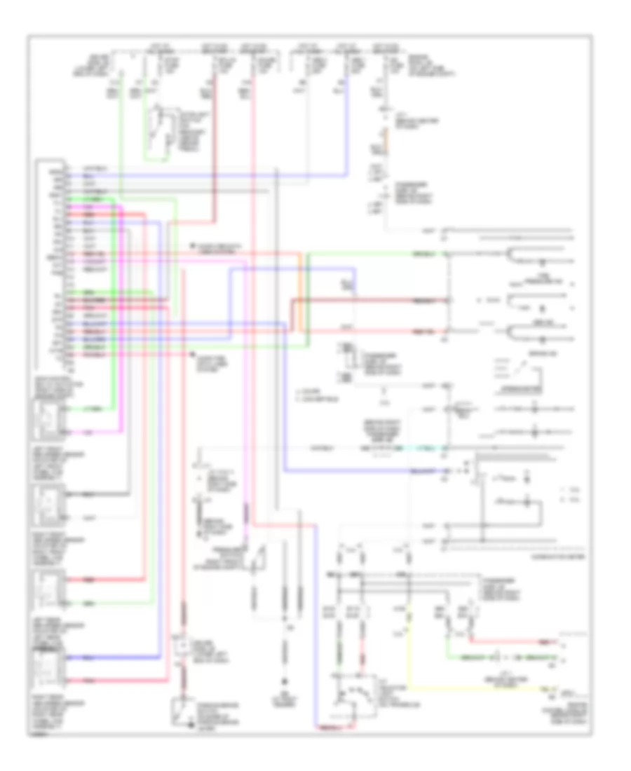
Anti-lock Brakes Wiring Diagram, with VSC (2 of 2) for Toyota Camry Solara SLE 2005
List of elements for Anti-lock Brakes Wiring Diagram, with VSC (2 of 2) for Toyota Camry Solara SLE 2005:
- (behind right side of dash) passenger side j/b
- (on steering column) steering sensor
- A66
- A67
- A96
- A97
- Abs ind
- B16
- B18
- B19
- B20
- B58
- B60
- B86
- B87
- B96
- B97
- Bat
- Brake ind
- Canh
- Canl
- Combination meter
- D j10
- Data link connector (dlc) 3 (below dash, left of steering column)
- Driver side j/b (lower left end of dash)
- E j11
- Ecu-b fuse 10a
- Ecu-ig fuse 10a
- Engine room j/b (on left side of engine compt)
- Ess
- F11
- F14
- Gauge 1 fuse 10a
- Gnd
- H16
- Hot at all times
- Hot in on or start
- Ig1
- Ig2 fuse 10a
- Im (behind right side of dash)
- J/c 1 (behind center of dash)
- J/c 10 & 11 (behind right side of dash)
- J/c 10 (behind right side of dash)
- J/c 12 (behind center of dash)
- J/c 5, 6, 7, 8 & 9 (behind front of center console)
- J10
- J11
- M13
- Passenger side j/b (behind right side of dash)
- Sil
- Slip ind
- Speedometer
- Tire pressure ind
- Vsc buzzer (behind center of dash)
- Vsc ind
- Vsc off ind
- Wfse
- Yaw rate sensor (below center console)
Anti-lock Brakes Wiring Diagram, without VSC for Toyota Camry Solara SLE 2005
List of elements for Anti-lock Brakes Wiring Diagram, without VSC for Toyota Camry Solara SLE 2005:
- (behind right side of dash) im
- (behind right side of dash) passenger side j/b
- (on transaxle)
- +bm
- +bs
- 2.4l
- 3.3l
- A/t indicator light switch l
- A109
- A66
- A96
- A99
- Abs 1 fuse 50a
- Abs 2 fuse 25a
- Abs ind
- B100
- B109
- B119
- B120
- B80
- B86 b76
- B87
- B89
- B90
- B96 b86
- B97
- B99
- Bean ecu
- Brake ind
- C13
- C14
- Combination meter
- Computer data lines system
- Convertible
- Coupe
- D j11
- D/g
- Driver side j/b (lower left end of dash)
- Eb (at right fender)
- Ebdw
- Ecu-ig fuse 10a
- Engine control module (behind right side of dash)
- Engine room j/b (on left side of engine compt)
- Fl+
- Fl-
- Fr+
- Fr-
- Gauge fuse 10a
- Gnd1
- Gnd2
- H16
- Hot at all times
- Hot in on or start
- Ig1
- Ig2 fuse 10a
- Init
- J/c 1 (behind center of dash)
- J/c 10 & 11 (behind right side of dash)
- J10 e
- Left front abs speed sensor (mounted on left front wheel hub assembly)
- Left rear abs speed sensor (mounted on left rear wheel hub assembly)
- Mpx1
- Parking brake switch (on base of parking brake lever)
- Passenger side j/b (behind right side of dash)
- Pkb
- Pnk
- Pressure switch (right front of engine compt)
- Red
- Right front abs speed sensor (mounted on right front wheel hub assembly)
- Right rear abs speed sensor (mounted on right rear wheel hub assembly)
- Rl+
- Rl-
- Rr+
- Rr-
- Skid control ecu w/ actuator (right side of engine compt)
- Sp1
- Speedometer
- Stop fuse 15a
- Stoplight switch (on bracket, above brake pedal)
- Stp
- Tire pressure ind
- Wtir