ANTI-LOCK BRAKES
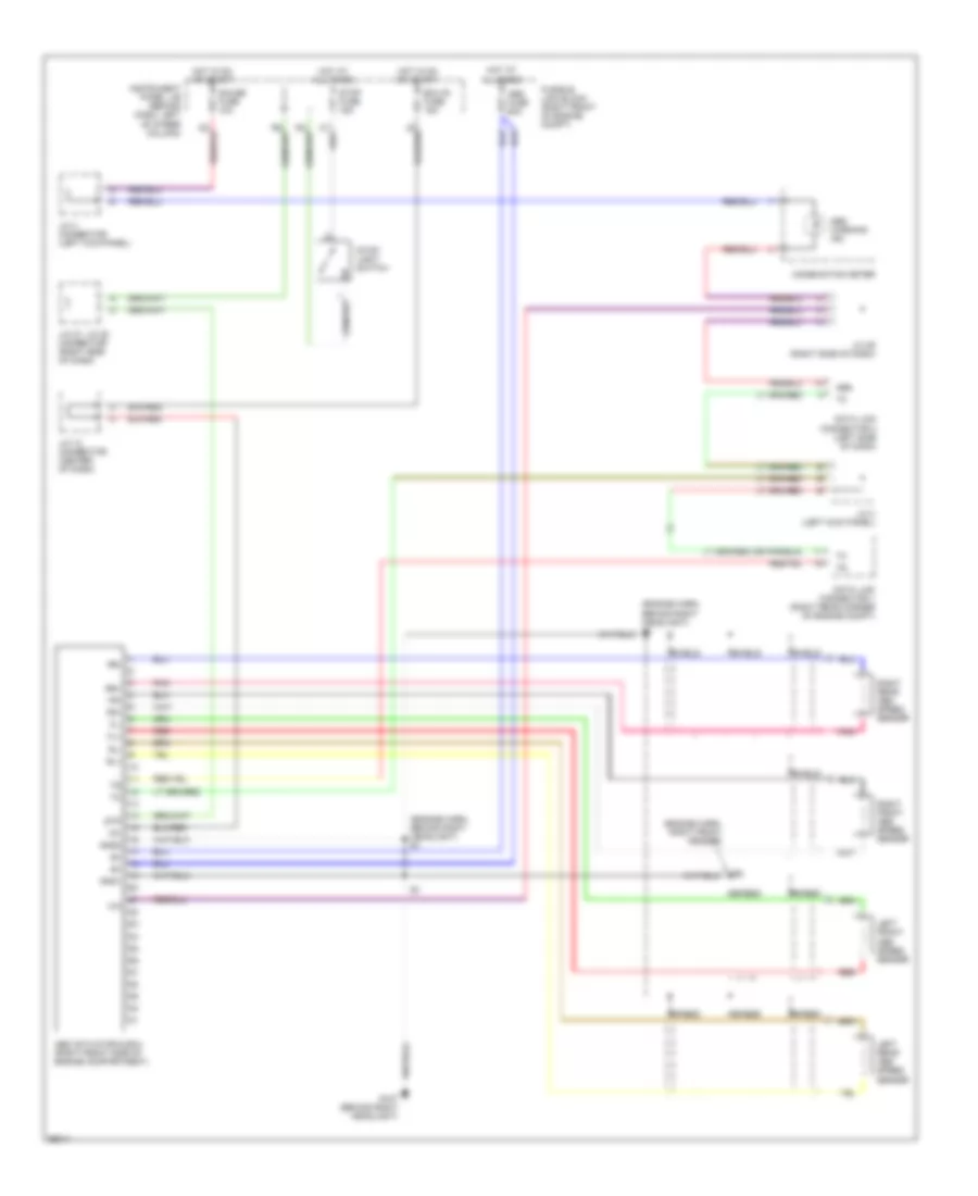
Anti-lock Brake Wiring Diagrams, TMC Made without Traction Control for Toyota Camry XLE 1998

List of elements for Anti-lock Brake Wiring Diagrams, TMC Made without Traction Control for Toyota Camry XLE 1998:
- (front right side of engine compartment) abs actuator
- (left side of dash) data link connector 2
- (right rear corner of engine compt) data link connector 1
- A18
- A19
- Abs
- Abs ecu (behind right side of glove box)
- Abs fuse 60a
- Abs motor relay
- Abs sol relay
- Abs warning ind
- Ast
- Combination meter
- D/g
- Ecu-ig fuse 15a
- Engine room r/b 3 (right front of engine compt)
- Fl+
- Fl-
- Fr+
- Fr-
- G107 (behind right headlight)
- G206
- Gauge fuse 10a
- Gnd
- Gnd2
- Hot at all times
- Hot in on or start
- Ig1
- Instrument panel j/b (behind dash, left of steering column)
- J/c 11 (center of dash)
- J/c 12 (center of dash)
- J/c 27, j/c 28 (right side of dash)
- J/c 29 (right side of dash)
- J/c 3 (left side of dash)
- J/c 4 (above left kick panel)
- J/c 7, j/c 8 (left side of dash)
- Left front abs speed sensor
- Left rear abs speed sensor
- Pnk
- Red
- Right front abs speed sensor
- Right rear abs speed sensor
- Rl+
- Rl-
- Rr+
- Rr-
- Sflh
- Sflr
- Sfrh
- Sfrr
- Shield
- Srlh
- Srlr
- Srrh
- Srrr
- Stop fuse 15a
- Stop light switch
- Stp
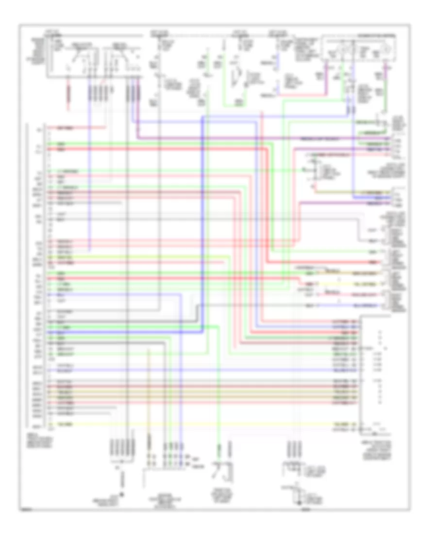
Anti-lock Brake Wiring Diagrams, TMM Made without Traction Control for Toyota Camry XLE 1998
List of elements for Anti-lock Brake Wiring Diagrams, TMM Made without Traction Control for Toyota Camry XLE 1998:
- (engine harn, behind right headlight) e1
- (engine harn, right front fender)
- Abs
- Abs actuator & ecu (right front side of engine compartment)
- Abs fuse 60a
- Abs warning ind
- Combination meter
- Data link connector 1 (right rear corner of engine compt)
- Data link connector 2 (left side of dash)
- Ecu-ig fuse 15a
- Fl+
- Fl-
- Fr+
- Fr-
- Fusible link block (right front of engine compt)
- G107 (behind right headlight)
- Gauge fuse 10a
- Gnd1
- Gnd2
- Hot at all times
- Hot in on or start
- Ig1
- Instrument panel j/b (behind dash, left of steer column)
- J/c 12 connector (center of dash)
- J/c 27, j/c 28 connector (right side of dash)
- J/c 29 (right side of dash)
- J/c 3 (left kick panel)
- J/c 4 connector (left kick panel)
- Left front abs speed sensor
- Left rear abs speed sensor
- Pnk
- Red
- Right front abs speed sensor
- Right rear abs speed sensor
- Rl+
- Rl-
- Rr+
- Rr-
- Shield
- Stop fuse 15a
- Stop- light switch
- Stp
Anti-lock Brake Wiring Diagrams, with Traction Control for Toyota Camry XLE 1998
List of elements for Anti-lock Brake Wiring Diagrams, with Traction Control for Toyota Camry XLE 1998:
- 1998-99
- A10
- A11
- A12
- A15
- A16
- A17
- Abs
- Abs & traction actuator (front right side of engine compartment)
- Abs & traction ecu (behind right side of dash)
- Abs fuse 60a
- Abs ind
- Abs motor relay
- Abs sol relay
- Ast
- C10
- Combination meter
- Csw
- D/g
- Data link connector 1 (right rear corner of engine compt)
- Data link connector 2 (left side of dash)
- Ecu-ig fuse 15a
- Efi+
- Efi-
- Engine control module (behind glove box)
- Engine room r/b 3 (right front of engine compt)
- Fl+
- Fl-
- Fr+
- Fr-
- G107 (behind right headlight)
- G206
- Gauge fuse 10a
- Gnd1
- Gnd2
- Gnd3
- Hot at all times
- Hot in on or start
- Ig1
- Ind
- Instrument panel j/b (behind dash, left of steering column)
- J/c 11 (center of dash)
- J/c 12 (center of dash)
- J/c 27, j/c 28 (right side of dash)
- J/c 29 (right side of dash)
- J/c 3 (above left kick panel)
- J/c 32 (behind right side of dash)
- J/c 4 (above left kick panel)
- J/c 7, j/c 8 (left side of dash)
- Left front abs speed sensor
- Left rear abs speed sensor
- Neo
- Red
- Right front abs speed sensor
- Right rear abs speed sensor
- Rl+
- Rl-
- Rr+
- Rr-
- Sflh
- Sflr
- Sfrh
- Sfrr
- Shield
- Slip ind
- Smc1
- Smc2
- Src1
- Src2
- Srlh
- Srlr
- Srrh
- Srrr
- Stop fuse 15a
- Stop- light switch
- Stp
- Trac off ind
- Traction off switch (left side of dash)
- Trc
- Trc+
- Trc-