ANTI-LOCK BRAKES
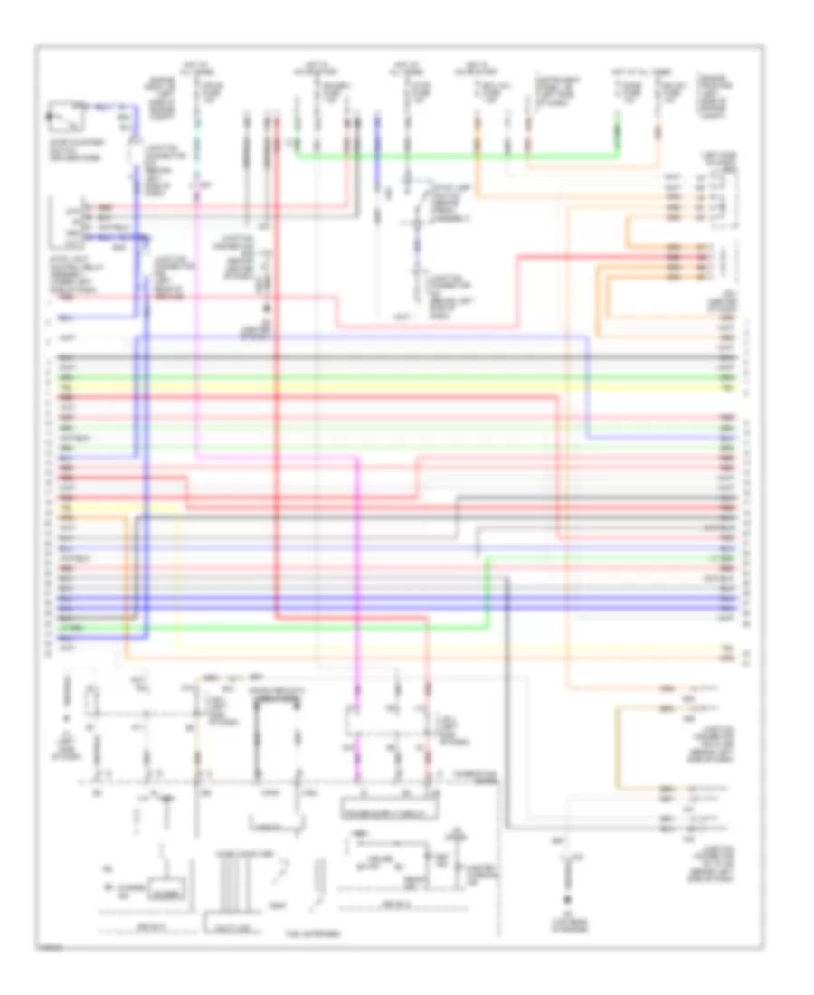
Anti-lock Brakes Wiring Diagram, Hybrid (1 of 4) for Toyota Camry XLE 2011

List of elements for Anti-lock Brakes Wiring Diagram, Hybrid (1 of 4) for Toyota Camry XLE 2011:
- (right "c" pillar) junction connector o21
- +bc
- +bi1
- +bo1
- A7 (right side of dash)
- A73
- A74
- A78
- A79
- Abs main 1 fuse 10a
- Abs main 3 fuse 10a
- Abs mtr1 fuse 50a
- Abs mtr1 relay
- Abs mtr2 fuse 40a
- Abs mtr2 relay
- Ae6
- Brake stroke simulator cylinder (left rear of engine compt)
- Bs1
- Canh
- Canl
- Computer data lines system
- Cty
- Cty+
- Ena
- Engine room r/b (left side of engine compt)
- Eo2
- Fail
- Fr+
- Fr-
- Fra+
- Fra-
- Frr+
- Frr-
- Gn1
- Gnd
- Gnd2
- Gnd3
- Hot at all times
- Ig1
- Left rear speed sensor (left rear hub assembly)
- Mr1
- Mtt
- Na1
- Nca
- Oa1
- Oa2
- Out 1
- Out 2
- Pac1
- Pck1
- Pfr
- Pmc1
- Pnk
- Prl
- R1+
- R1-
- R3+
- Red
- Right front speed sensor (right front hub assembly)
- Rl+
- Rl-
- Rla+
- Rla-
- Rlr+
- Rlr-
- Sg1
- Short connector a78 & a79 (right side of engine compt)
- Skid control ecu (right front of of engine compt)
- Smc1
- Spi
- Stp
- Vbz
- Vcm
- Vsc warning buzzer (left side of dash)
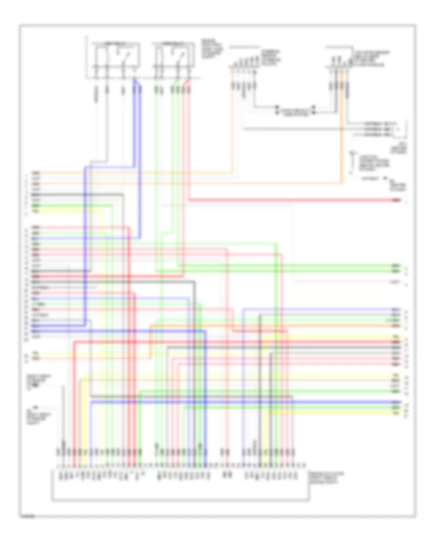
Anti-lock Brakes Wiring Diagram, Hybrid (2 of 4) for Toyota Camry XLE 2011
List of elements for Anti-lock Brakes Wiring Diagram, Hybrid (2 of 4) for Toyota Camry XLE 2011:
- (left side of dash) j/b 3
- +b (dome)
- A41
- A42
- A58
- Ae2
- Buzzer
- C6 (top rear of engine)
- Ca3
- Can i/f
- Canh
- Canl
- Charge ind
- Combination meter
- Computer data lines system
- Cruise ind
- D10
- D13
- Dome fuse 10a
- Door courtesy switch (driver's side)
- Drive ic
- E2 (center of dash)
- E40
- Ea1
- Ecu ig 2 fuse 7.5a
- Ecu-b 1 fuse 10a
- En2
- Engine room j/b (left side of engine compt)
- Engine room r/b (left side of engine compt)
- F1 (left side of dash)
- F10
- F19
- Fuel expenses
- G12
- Gauge 2 fuse 7.5a
- Gnd
- Hot at all times
- Hot in on or start
- Ig+
- Ig2
- Instrument panel j/b (left side of dash)
- J/b 3 (left side of dash)
- J/b 4 (center of dash)
- Junction connector a41 & a42 (behind left side of dash)
- Junction connector a41 (behind left side of dash)
- Junction connector e40 & a58 (behind left side of dash)
- Junction connector e74 (behind left side of dash)
- Junction connector n28 (left rear of vehicle)
- L12
- Master warning ind
- Micro computer
- Mpx-b fuse 10a
- Multi lcd
- Out
- P11
- Q12
- Ready ind
- Red
- Set ind
- Stop fuse 10a
- Stop lamp switch (brake pedal assembly)
- Stop light control relay assembly (under left side of dash)
- Stp
- Temp
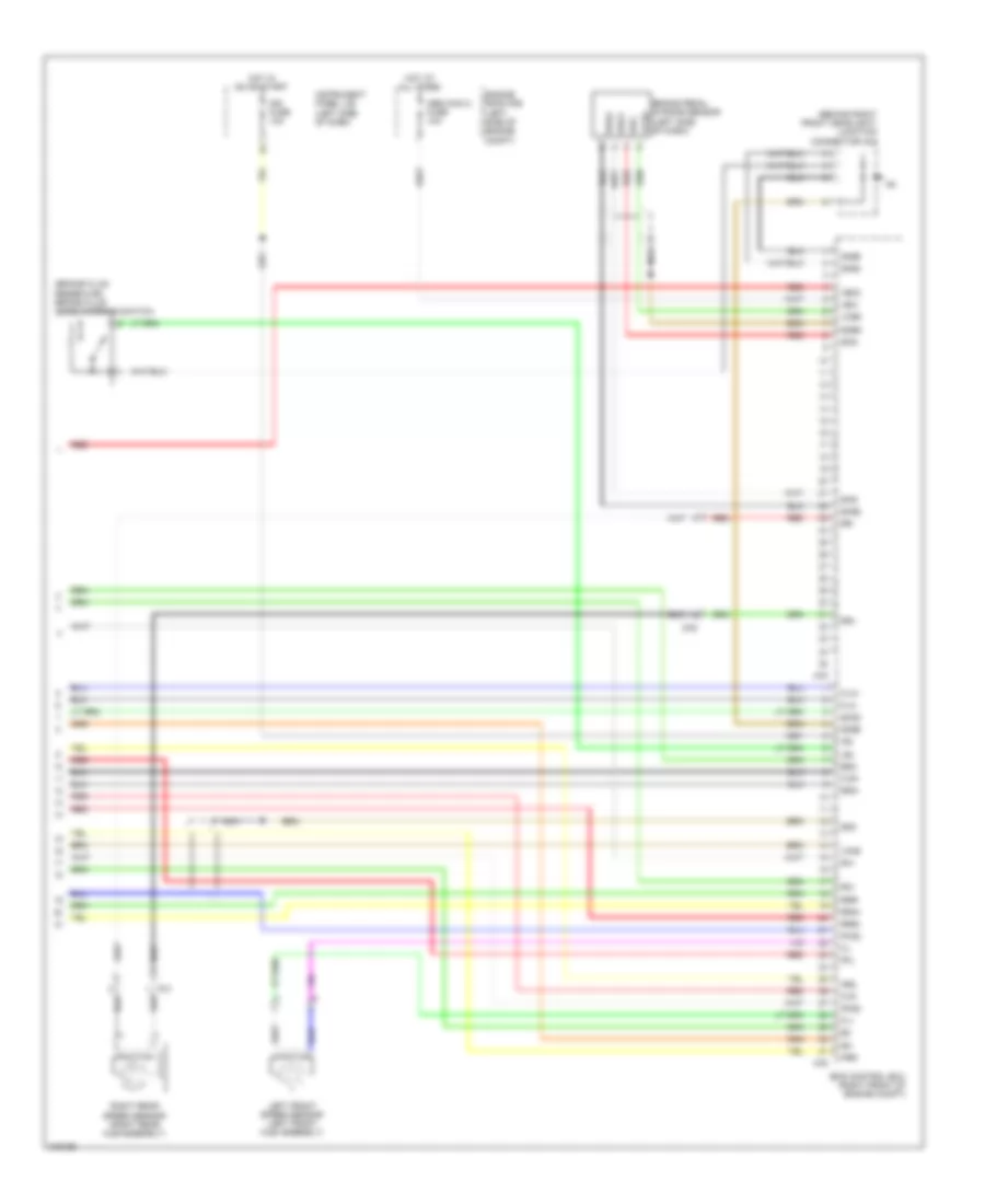
Anti-lock Brakes Wiring Diagram, Hybrid (3 of 4) for Toyota Camry XLE 2011
List of elements for Anti-lock Brakes Wiring Diagram, Hybrid (3 of 4) for Toyota Camry XLE 2011:
- (right front of engine compt) a4
- A8 (right front of engine compt)
- Abs1 relay
- Abs2 relay
- Bat
- Bm1
- Bm2
- Brake actuator (right side of engine compt)
- Bs1
- Bs2
- Canh
- Canl
- Computer data lines system
- E2 (center of dash)
- Engine room r/b 3 (right side of engine compt)
- Ess
- Fla+
- Fla-
- Flr+
- Flr-
- Fra+
- Fra-
- Frr+
- Frr-
- Gnd
- Gnd1
- Gnd2
- J/b 4 (center of dash)
- Junction connector e49 (behind center of dash)
- Mtt
- Pac1
- Pck1
- Pck2
- Pfl
- Pfr
- Pmc1
- Pmc2
- Prl
- Prr
- Red
- Rla+
- Rla-
- Rlr+
- Rlr-
- Rra+
- Rra-
- Rrr+
- Rrr-
- Smc1
- Smc2
- Steering sensor (steering column)
- Vcm
- Vcm2
- Yaw rate sensor (below rear of center floor console)
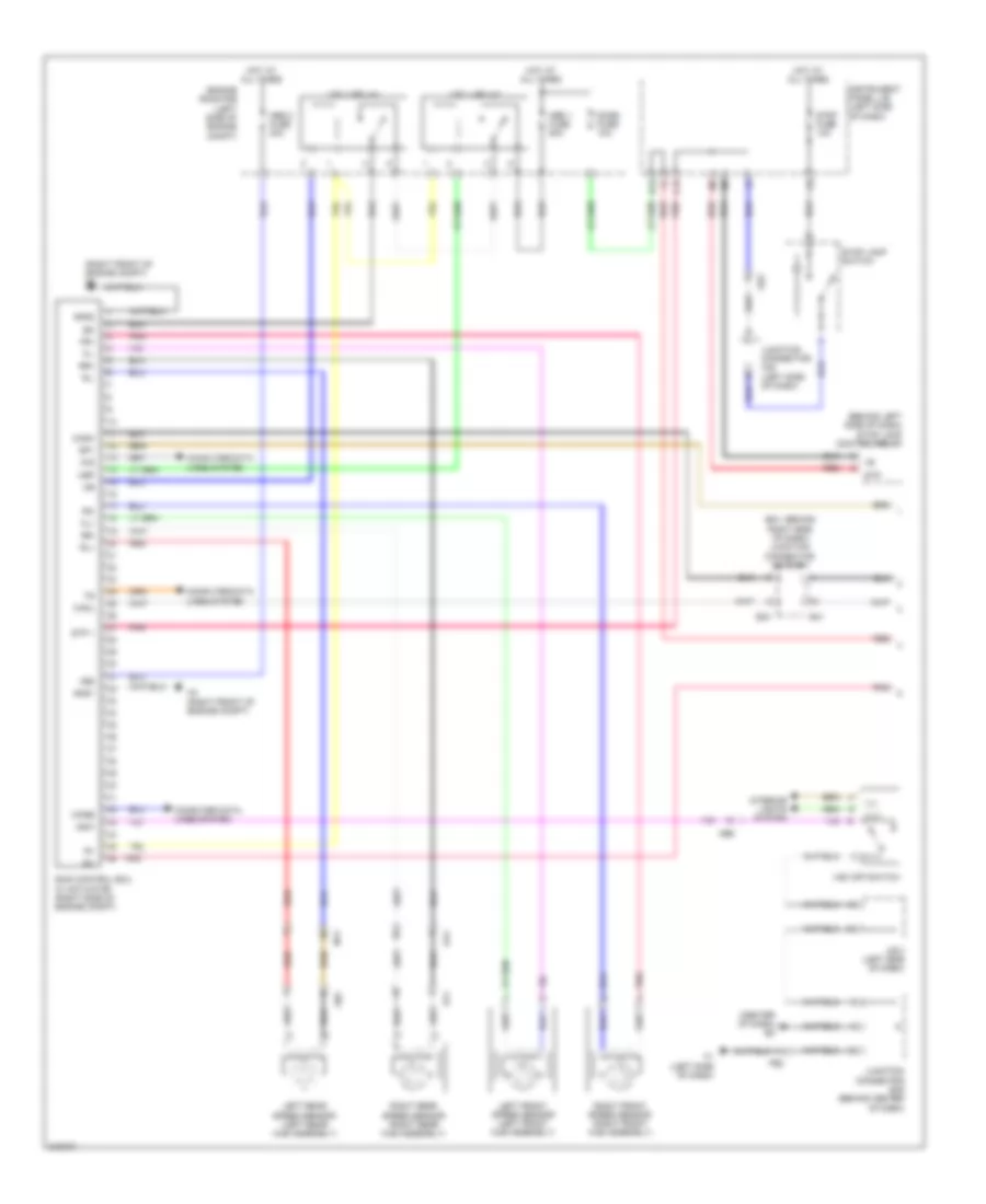
Anti-lock Brakes Wiring Diagram, Hybrid (4 of 4) for Toyota Camry XLE 2011
List of elements for Anti-lock Brakes Wiring Diagram, Hybrid (4 of 4) for Toyota Camry XLE 2011:
- (behind right front headlight) junction connector a44
- (brake fluid reservoir) brake fluid level warning switch
- +bi2
- +bo2
- A75
- A76
- Abs main 2 fuse 10a
- Brake pedal stroke sensor (left side of dash)
- Bs2
- Engine room r/b (left side of engine compt)
- Fl+
- Fl-
- Fla+
- Fla-
- Flr+
- Flr-
- Fo1
- Gnd4
- Gnd5
- Gnd6
- Hot at all times
- Hot in on or start
- Ig2
- Ign fuse 10a
- Instrument panel j/b (left side of dash)
- Lbl
- Left front speed sensor (left front hub assembly)
- Mr2
- Nca
- Oa2
- Pck2
- Pfl
- Pmc2
- Prr
- R2+
- R2-
- R4+
- Red
- Right rear speed sensor (right rear hub assembly)
- Rr+
- Rr-
- Rra+
- Rra-
- Rrr+
- Rrr-
- Sg2
- Sgsk
- Skg
- Skid control ecu (right front of engine compt)
- Sks
- Sks1
- Sks2
- Smc2
- Vcm2
- Vcsk
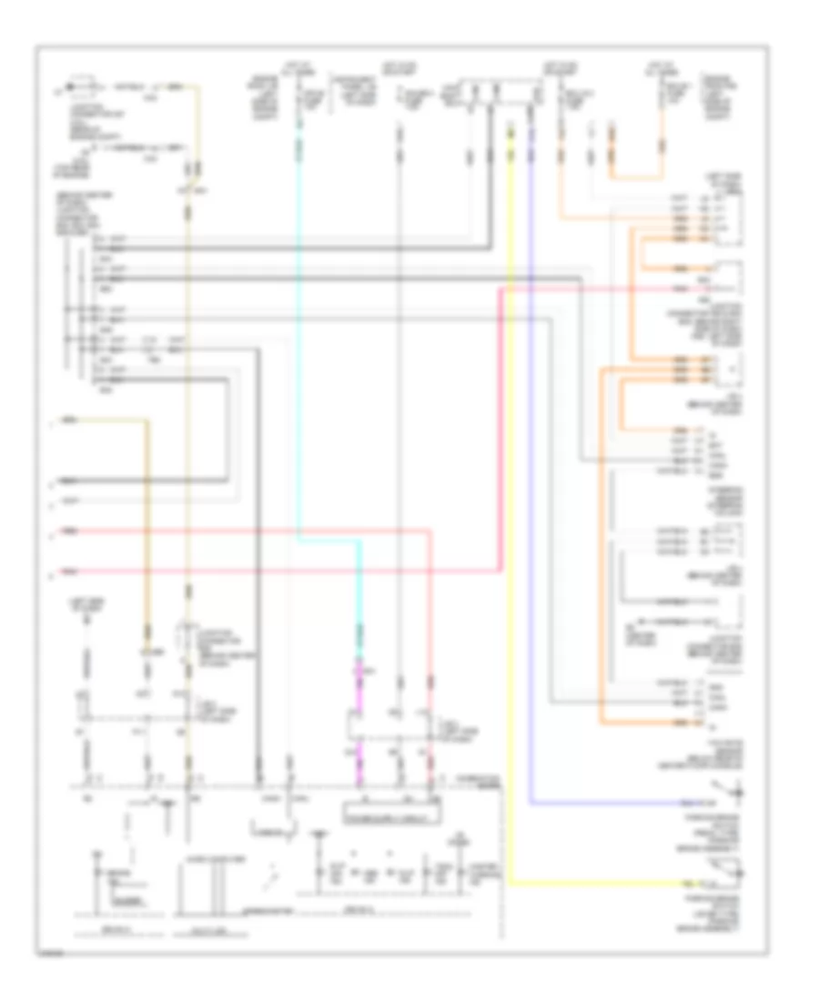
Anti-lock Brakes Wiring Diagram, TMC Made (1 of 2) for Toyota Camry XLE 2011
List of elements for Anti-lock Brakes Wiring Diagram, TMC Made (1 of 2) for Toyota Camry XLE 2011:
- (behind left side of dash) stop lamp control relay
- (center of dash) e2
- (e41: behind right side of dash) junction connector a40 & e41
- (right front of engine compt) a4
- +bs
- A4 (right front of engine compt)
- Abs 1 fuse 50a
- Abs 2 fuse 30a
- Ae2
- Ae6
- C13
- Canh
- Canl
- Computer data lines system
- Csw
- D/g
- D13
- Dome fuse 10a
- E40
- E41
- Engine room r/b (left side of engine compt)
- F1 (left side of dash)
- Fe2
- Fl+
- Fl-
- Fo1
- Fr+
- Fr-
- Gn1
- Gnd1
- Gnd2
- Hot at all times
- Ig1
- Ill+
- Ill-
- Instrument panel j/b (left side of dash)
- Interior lights system
- J/b 3 (left side of dash)
- Junction connector a42 (left side of dash)
- Junction connector e49 (behind center of dash)
- Left front speed sensor (left front hub assembly)
- Left rear speed sensor (left rear hub assembly)
- Mrf
- Na1
- Oa1
- Pnk
- Red
- Right front speed sensor (right front hub assembly)
- Right rear speed sensor (right rear hub assembly)
- Rl+
- Rl-
- Rr+
- Rr-
- Skid control ecu w/ actuator (right side of engine compt)
- Sp1
- Stop fuse 10a
- Stop lamp switch
- Stp
- Stp 1
- Vsc 1 relay
- Vsc 2 relay
- Vsc off switch
- Wfse
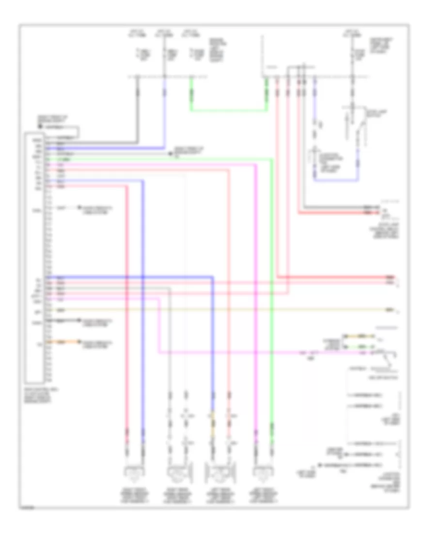
Anti-lock Brakes Wiring Diagram, TMC Made (2 of 2) for Toyota Camry XLE 2011
List of elements for Anti-lock Brakes Wiring Diagram, TMC Made (2 of 2) for Toyota Camry XLE 2011:
- (behind center of dash) junction connector e42, e43, e44, e46 & e63
- (center of dash)
- (left side of dash) f1
- (left side of dash) j/b 3
- +b (dome)
- A58
- Abs ind
- Ae6
- Bat
- Brake ind
- Buzzer
- C14
- C6 (2.5l) (top rear of engine)
- Ca3
- Can i/f
- Canh
- Canl
- Combination meter
- D10
- Drive ic
- E40
- E42
- E43
- E44
- E46
- E63
- Ea1
- Ecu ig 2 fuse 7.5a
- Ecu-b 1 fuse 10a
- Engine room j/b (left side of engine compt)
- Engine room r/b (left side of engine compt)
- Ess
- F19
- Fe2
- G12
- Gauge 2 fuse 7.5a
- Gnd
- Hot at all times
- Hot in on or start
- Ig+
- Ig2
- Instrument panel j/b (left side of dash)
- J/b 3 (left side of dash)
- J/b 4 (behind center of dash)
- Junction connector a58 & e40 (e40: behind right side of dash) (a58: left side of dash)
- Junction connector c57 (3.5l) (rear of engine compt)
- Junction connector e48 (behind center of dash)
- Junction connector e49 (behind center of dash)
- L12
- Main body ecu
- Master warning ind
- Micro computer
- Mpx-b fuse 10a
- Multi lcd
- P11
- Parking brake switch (lever type) (parking brake assembly)
- Parking brake switch (pedal type) (parking brake assembly)
- Pkb
- Pnk
- Q12
- Red
- Slip ind
- Slip off ind
- Speedometer
- Steering sensor (steering column)
- Trac off ind
- Yaw rate sensor (below rear of center floor console)
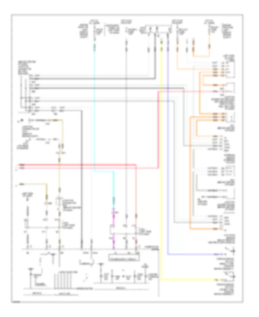
Anti-lock Brakes Wiring Diagram, TMMK Made (1 of 2) for Toyota Camry XLE 2011
List of elements for Anti-lock Brakes Wiring Diagram, TMMK Made (1 of 2) for Toyota Camry XLE 2011:
- (center of dash) e2
- (right front of engine compt) a4
- +bm
- +bs
- Abs 1 fuse 50a
- Abs 2 fuse 30a
- Ae2
- Ae6
- C13
- Canh
- Canl
- Computer data lines system
- Csw
- D13
- Dome fuse 10a
- Engine room r/b (left side of engine compt)
- F1 (left side of dash)
- Fe2
- Fl+
- Fl-
- Fo1
- Fr+
- Fr-
- Gn1
- Gnd1
- Gnd2
- Hot at all times
- Ig1
- Ill+
- Ill-
- Instrument panel j/b (left side of dash)
- Interior lights system
- J/b 3 (left side of dash)
- Junction connector a42 (left side of dash)
- Junction connector e49 (behind center of dash)
- Left front speed sensor (left front hub assembly)
- Left rear speed sensor (left rear hub assembly)
- Na1
- Oa1
- Pnk
- Red
- Right front speed sensor (right front hub assembly)
- Right rear speed sensor (right rear hub assembly)
- Rl+
- Rl-
- Rr+
- Rr-
- Skid control ecu w/ actuator (right side of engine compt)
- Sp1
- Stop fuse 10a
- Stop lamp control relay (behind left side of dash)
- Stop lamp switch
- Stp
- Stp 1
- Vsc off switch
Anti-lock Brakes Wiring Diagram, TMMK Made (2 of 2) for Toyota Camry XLE 2011
List of elements for Anti-lock Brakes Wiring Diagram, TMMK Made (2 of 2) for Toyota Camry XLE 2011:
- (behind center of dash) junction connector e43, e44, e46 & e63
- (left side of dash) f1
- (left side of dash) j/b 3
- +b (dome)
- A58
- Abs ind
- Ae6
- Bat
- Brake ind
- Buzzer
- C14
- C6 (2.5l) (top rear of engine)
- Ca3
- Can i/f
- Canh
- Canl
- Combination meter
- D10
- Drive ic
- E2 (center of dash)
- E40
- E43
- E44
- E46
- E63
- Ea1
- Ecu ig 2 fuse 7.5a
- Ecu-b 1 fuse 10a
- Engine room j/b (left side of engine compt)
- Engine room r/b (left side of engine compt)
- Ess
- F19
- Fe2
- G12
- Gauge 2 fuse 7.5a
- Gnd
- Hot at all times
- Hot in on or start
- Ig+
- Ig2
- Instrument panel j/b (left side of dash)
- J/b 3 (left side of dash)
- J/b 4 (behind center of dash)
- Junction connector a58 & e40 (e40: behind right side of dash) (a58: left side of dash)
- Junction connector c57 (3.5l) (rear of engine compt)
- Junction connector e48 (behind center of dash)
- Junction connector e49 (behind center of dash)
- L12
- Main body ecu
- Master warning ind
- Micro computer
- Mpx-b fuse 10a
- Multi lcd
- P11
- Parking brake switch (lever type) (parking brake assembly)
- Parking brake switch (pedal type) (parking brake assembly)
- Pkb
- Pnk
- Q12
- Red
- Slip ind
- Slip off ind
- Speedometer
- Steering sensor (steering column)
- Trac off ind
- Yaw rate sensor (below rear of center floor console)