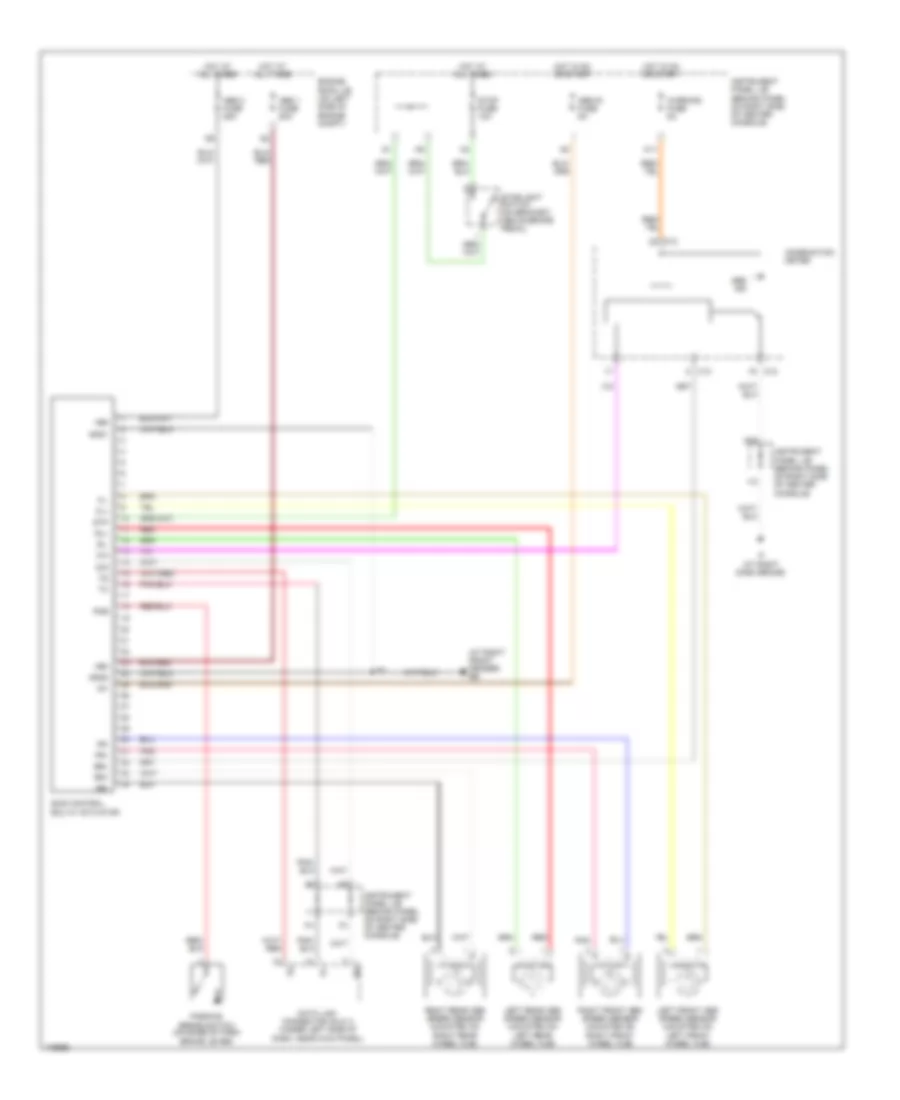
ANTI-LOCK BRAKES
Anti-lock Brakes Wiring Diagram for Toyota Celica GT-S 2003
List of elements for Anti-lock Brakes Wiring Diagram for Toyota Celica GT-S 2003:
- (at right front fender) eb
- +bm
- +bs
- Abs 1 fuse 50a
- Abs 2 fuse 25a
- Abs ind
- Abs-ig fuse 5a
- Brl
- C12
- C13
- Combination meter
- D/g
- Data link connector (dlc) 3 (under left side of dash, near kick panel)
- Engine room j/b (on left side of engine compt)
- Fl+
- Fl-
- Fr+
- Fr-
- Gnd1
- Gnd2
- Hot at all times
- Hot in on or start
- I12
- If (at right dash brace)
- Ig1
- Instrument panel j/b (behind panel on right side of center console)
- Left front abs speed sensor (mounted on left front wheel hub)
- Left rear abs speed sensor (mounted on left rear wheel hub)
- M11
- M20
- Parking brake switch (on base of park brake lever)
- Pkb
- Pnk
- Red
- Right front abs speed sensor (mounted on right front wheel hub)
- Right rear abs speed sensor (mounted on right rear wheel hub)
- Rl+
- Rl-
- Rr+
- Rr-
- Sil
- Skid control ecu w/ actuator
- Stop fuse 10a
- Stoplight switch (on bracket, above brake pedal)
- Stp
- Warning fuse 5a
 English