ANTI-LOCK BRAKES
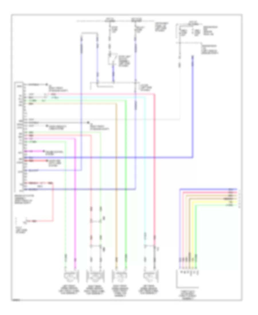
Anti-lock Brakes Wiring Diagram, NUMMI Made with VSC (1 of 2) for Toyota Corolla S 2012

List of elements for Anti-lock Brakes Wiring Diagram, NUMMI Made with VSC (1 of 2) for Toyota Corolla S 2012:
- (right front of engine compt) a4
- +bm
- +bs
- A4 (right front of engine compt)
- A50
- Abs 1 fuse 50a
- Abs 3 fuse 30a
- Ae12
- Al1
- Am1
- B12
- B18
- B19
- B21
- B24
- B31
- B4 (top of engine)
- Ba2
- Brake actuator assembly (right front of engine compt)
- Canh
- Canl
- Computer data lines system
- Crank position sensor (lower left front of engine)
- Cruise control system
- Csw
- Dlc 3 (left side of dash)
- Ecm (left side of engine compt)
- Ecu-ig 1 fuse 10a
- Ecu-ig 2 fuse 10a
- Engine room j/b (left side of engine compt)
- Engine room r/b (engine room j/b)
- Eta
- Fl+
- Fl-
- Fr+
- Fr-
- Ge01
- Gnd1
- Gnd2
- Hot at all times
- Hot in on or start
- Ig1
- Instrument panel j/b (left side of dash)
- J/c a45 (left side of dash)
- Left front speed sensor (left front wheel hub assembly)
- Left rear speed sensor (left rear wheel hub assembly)
- Ne+
- Ne-
- Park/neutral position switch (a/t) (left side of transaxle)
- Pnk
- Red
- Right front speed sensor (right front wheel hub assembly)
- Right rear speed sensor (right rear wheel hub assembly)
- Rl+
- Rl-
- Rr+
- Rr-
- Sp1
- Stop fuse 10a
- Stop light switch assembly
- Stp
- Throttle w/ motor body (throttle body assembly)
- Vcta
- Vl2
- Vta
- Vta1
- Vta2
- Wm2
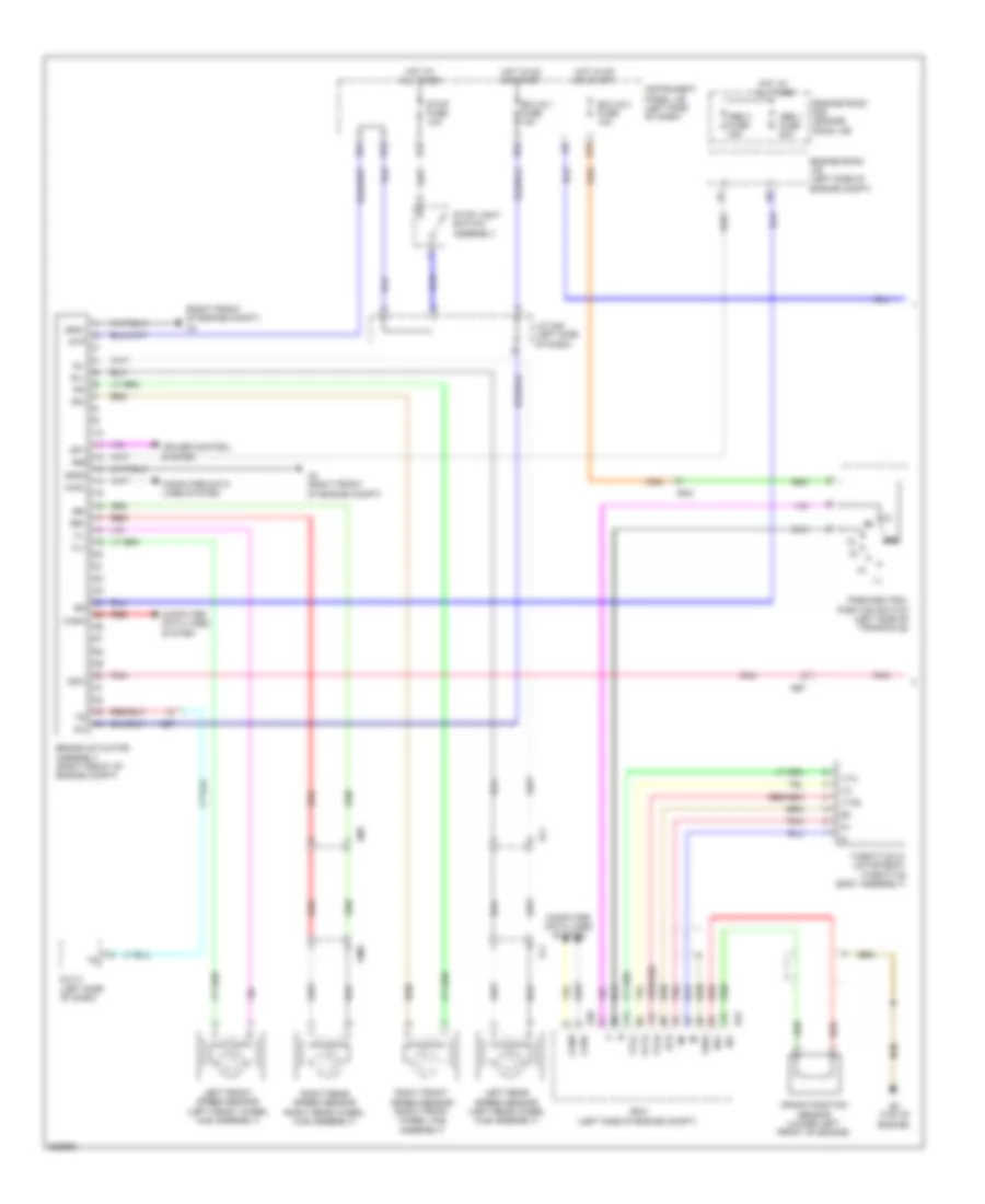
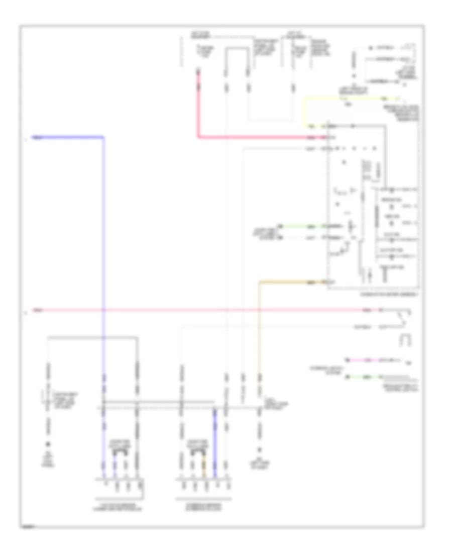
Anti-lock Brakes Wiring Diagram, NUMMI Made with VSC (2 of 2) for Toyota Corolla S 2012
List of elements for Anti-lock Brakes Wiring Diagram, NUMMI Made with VSC (2 of 2) for Toyota Corolla S 2012:
- 5v ic
- 5v+b
- A1 (left front of engine compt)
- Abs ind
- Ae3
- B30
- Bat
- Brake fluid level warning switch (brake fluid reservoir)
- Brake ind
- Buzzer
- Can i/f
- Canh
- Canl
- Combination meter assembly
- Computer data lines system
- Cpu
- E2 (left side of dash)
- Ecu-b fuse 10a
- Engine room r/b (engine room j/b)
- Ess
- Gnd
- H12
- Hot at all times
- Hot in on or start
- I/f
- Ig+
- Ig1
- Instrument panel j/b (left side of dash)
- Interior lights system
- J/c a46 (left side of dash)
- J/c e107 (right side of dash)
- Led driver
- Meter fuse 7.5a
- Red
- Slip ind
- Slip off ind
- Steering sensor (steering column)
- Trac off ind
- Vehicle stability control switch
- Yaw rate sensor (under center console)
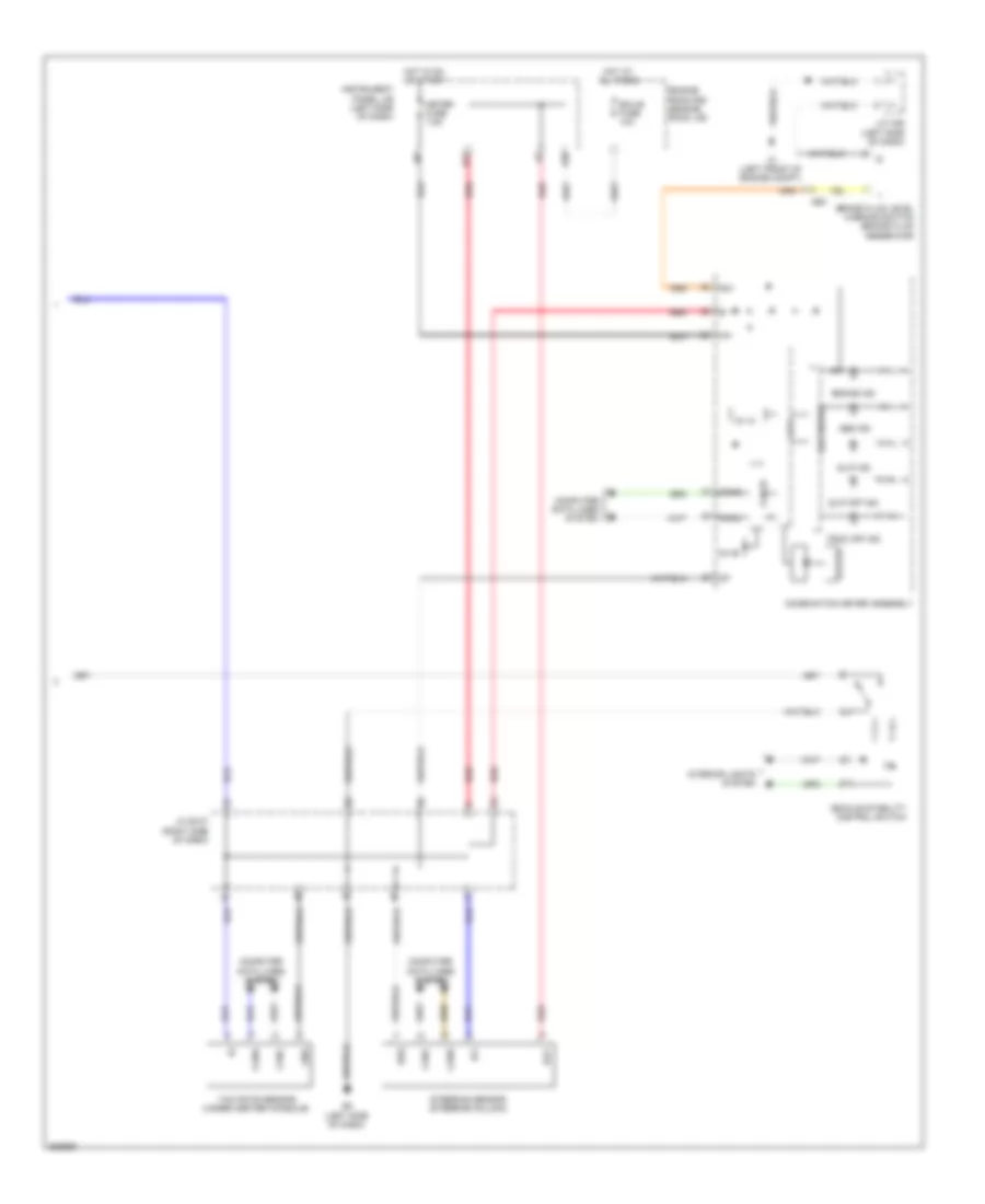
Anti-lock Brakes Wiring Diagram, NUMMI Made without VSC (1 of 2) for Toyota Corolla S 2012
List of elements for Anti-lock Brakes Wiring Diagram, NUMMI Made without VSC (1 of 2) for Toyota Corolla S 2012:
- +bm
- +bs
- A4 (right front of engine compt)
- Abs 1 fuse 50a
- Abs 3 fuse 30a
- Ae12
- Al1
- Am1
- B12
- B18
- B21
- B24
- Brake actuator assembly (right front of engine compt)
- Canh
- Canl
- Computer data lines system
- Cruise control system
- Dlc 3 (left side of dash)
- Ecu-ig 1 fuse 10a
- Engine room j/b (left side of engine compt)
- Engine room r/b (engine room j/b)
- Fl+
- Fl-
- Fr+
- Fr-
- Gnd1
- Gnd2
- Hot at all times
- Hot in on or start
- Ig1
- Instrument panel j/b (left side of dash)
- J/c a45 (left side of dash)
- Left front speed sensor (left front wheel hub assembly)
- Left rear speed sensor (left rear wheel hub assembly)
- Pnk
- Red
- Right front speed sensor (right front wheel hub assembly)
- Right rear speed sensor (right rear wheel hub assembly)
- Rl+
- Rl-
- Rr+
- Rr-
- Sp1
- Stop fuse 10a
- Stop light switch assembly (left side of dash)
- Stp
- Throttle w/ motor body (throttle body assembly)
- Vl2
- Vta
- Vta2
- Wm2
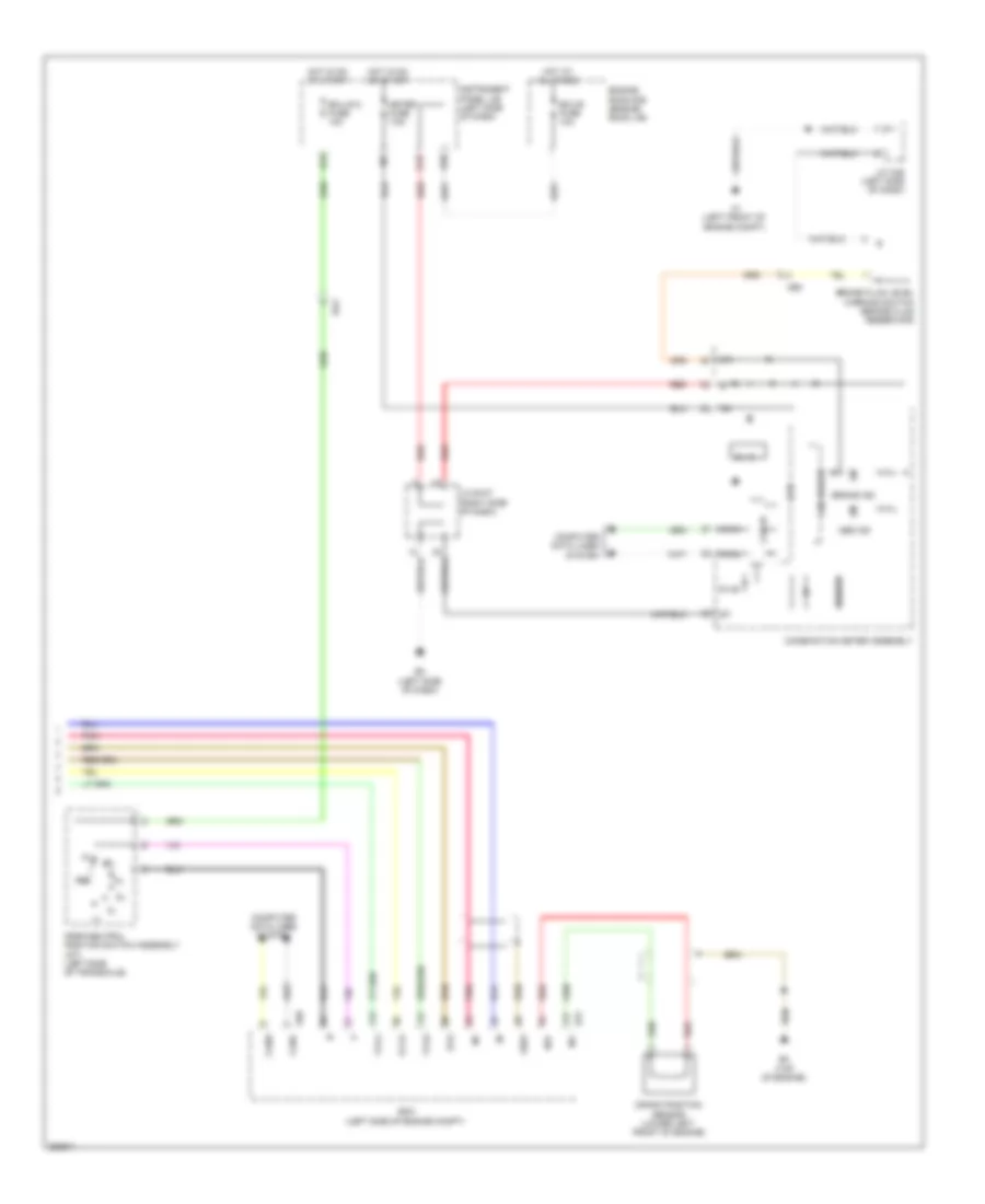
Anti-lock Brakes Wiring Diagram, NUMMI Made without VSC (2 of 2) for Toyota Corolla S 2012
List of elements for Anti-lock Brakes Wiring Diagram, NUMMI Made without VSC (2 of 2) for Toyota Corolla S 2012:
- 5v ic
- 5v+b
- A1 (left front of engine compt)
- A50
- Abs ind
- Ae3
- B19
- B30
- B31
- B4 (top of engine)
- Ba2
- Brake fluid level warning switch (brake fluid reservoir)
- Brake ind
- Buzzer
- Can i/f
- Canh
- Canl
- Combination meter assembly
- Computer data lines system
- Cpu
- Crank position sensor (lower left front of engine)
- E2 (left side of dash)
- Ecm (left side of engine compt)
- Ecu-b fuse 10a
- Ecu-ig 2 fuse 10a
- Engine room r/b (engine room j/b)
- Eta
- Ge01
- H12
- Hot at all times
- Hot in on or start
- I/f
- Ig+
- Instrument panel j/b (left side of dash)
- J/c a46 (left side of dash)
- J/c e107 (right side of dash)
- Led driver
- Meter fuse 7.5a
- Ne+
- Ne-
- Park/neutral position switch assembly (a/t) (left side of transaxle)
- Pnk
- Red
- Vcta
- Vta1
- Vta2
Anti-lock Brakes Wiring Diagram, TMC Made (1 of 2) for Toyota Corolla S 2012
List of elements for Anti-lock Brakes Wiring Diagram, TMC Made (1 of 2) for Toyota Corolla S 2012:
- (right front of engine compt) a4
- +bs
- A4 (right front of engine compt)
- A50
- Abs 1 fuse 50a
- Abs 3 fuse 30a
- Ae7
- Al1
- Am1
- B12
- B18
- B19
- B21
- B24
- B31
- B4 (top of engine)
- Ba2
- Brake actuator assembly (right front of engine compt)
- Canh
- Canl
- Computer data lines system
- Crank position sensor (lower left front of engine)
- Cruise control system
- Csw
- Dlc 3 (left side of dash)
- Ecm (left side of engine compt)
- Ecu-ig 1 fuse 10a
- Ecu-ig 2 fuse 10a
- Engine room j/b (left side of engine compt)
- Engine room r/b (engine room j/b)
- Eta
- Fl+
- Fl-
- Fr+
- Fr-
- Ge01
- Gnd1
- Gnd2
- Hot at all times
- Hot in on or start
- Ig1
- Instrument panel j/b (left side of dash)
- J/c a45 (left side of dash)
- Left front speed sensor (left front wheel hub assembly)
- Left rear speed sensor (left rear wheel hub assembly)
- Ne+
- Ne-
- Park/neutral position switch (left side of transaxle)
- Pnk
- Red
- Right front speed sensor (right front wheel hub assembly)
- Right rear speed sensor (right rear wheel hub assembly)
- Rl+
- Rl-
- Rr+
- Rr-
- Sp1
- Stop fuse 10a
- Stop light switch assembly
- Stp
- Throttle w/ motor body (throttle body assembly)
- Vcta
- Vl1
- Vta
- Vta1
- Vta2
- Wm1
Anti-lock Brakes Wiring Diagram, TMC Made (2 of 2) for Toyota Corolla S 2012
List of elements for Anti-lock Brakes Wiring Diagram, TMC Made (2 of 2) for Toyota Corolla S 2012:
- 5v ic
- 5v+b
- A1 (left front of engine compt)
- A69
- A70
- Abs ind
- Ae3
- B19
- B25
- B30
- B32
- B33
- B35
- B36
- B58
- Bat
- Brake fluid level warning switch (brake fluid reservoir)
- Brake ind
- Buzzer
- C15
- C21
- Can i/f
- Canh
- Canl
- Combination meter assembly
- Computer data lines system
- Cpu
- Display
- E1 (left kick panel)
- E17
- E2 (left side of dash)
- Ecu-b fuse 10a
- Engine room r/b (engine room j/b)
- Ess
- Gnd
- H12
- Hot at all times
- Hot in on or start
- I/f
- Ig+
- Ig1
- Instrument panel j/b (left side of dash)
- Interior lights system
- J/b 4 (right side of dash)
- J/c a46 (left side of dash)
- Led driver
- Meter fuse 7.5a
- Pnk
- Slip ind
- Slip off ind
- Steering sensor (steering column)
- Trac off ind
- Vehicle stability control switch
- Yaw rate sensor (under center console)