ANTI-LOCK BRAKES
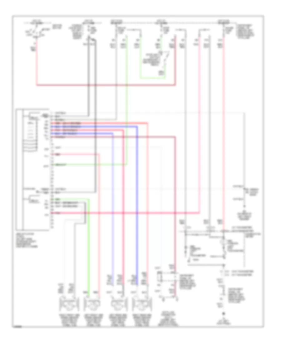
Anti-lock Brakes Wiring Diagram for Toyota ECHO 2005
List of elements for Anti-lock Brakes Wiring Diagram for Toyota ECHO 2005:
- (hatch back)
- (sedan)
- (w/ tachometer)
- (w/o tachometer)
- +bm
- Abs actuator w/ ecu (on left side of engine compt, near brake master cylinder)
- Abs fuse 60a
- Abs warning light (w/ tachometer)
- Abs warning light (w/o tachometer)
- Acc
- C13
- C14
- Combination meter
- D/g
- Data link connector (dlc) 3 (under left side of dash, near kick panel)
- Ec (on rear of left front fender)
- Ecu-ig fuse 7.5a
- F12
- Fl+
- Fl-
- Fr+
- Fr-
- Fusible link block (on left side of engine compt)
- G13
- Gauge fuse 10a
- Gnd1 +bs
- Gnd2
- Hot at all times
- Hot in on or start
- Id (at left kick panel)
- Ig1
- Ignition switch
- Instrument panel j/b (behind left side of dash, near base of "a" pillar)
- Left front abs speed sensor (mounted on left front wheel hub)
- Left rear abs speed sensor (mounted on left rear wheel hub)
- Lock
- Off
- P10
- Pnk
- Red
- Relay
- Right front abs speed sensor (mounted on right front wheel hub)
- Right rear abs speed sensor (mounted on right rear wheel hub)
- Rl+
- Rl-
- Rr+
- Rr-
- Sil
- Start
- Stop fuse 10a
- Stoplight switch (on bracket, above brake pedal)
- Stp
 English