ANTI-LOCK BRAKES
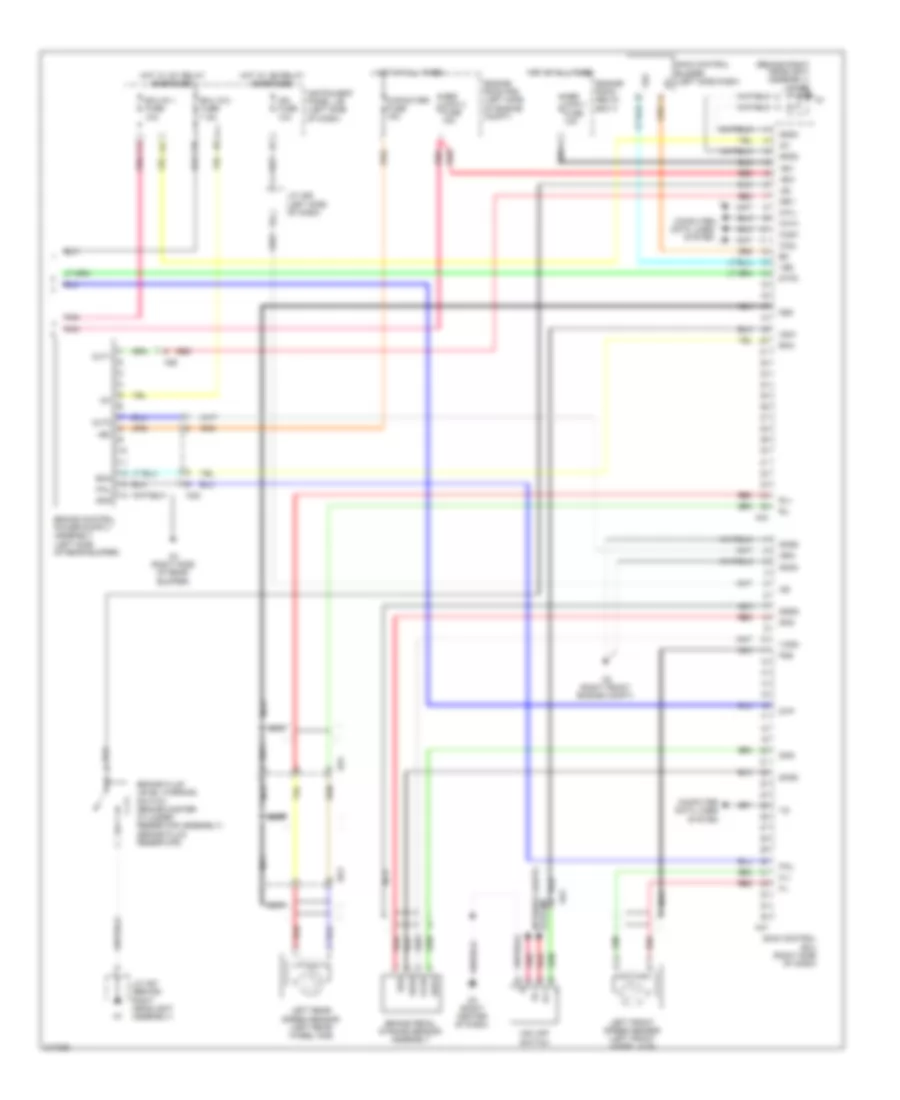
Anti-lock Brakes Wiring Diagram, Except Hybrid (1 of 2) for Toyota Highlander Hybrid 2011

List of elements for Anti-lock Brakes Wiring Diagram, Except Hybrid (1 of 2) for Toyota Highlander Hybrid 2011:
- +bs
- 2wd
- 4wd
- A2 (behind right front headlight)
- A3 (behind left front headlight)
- A41
- Ad11
- Ad4
- Ad9
- An1
- Brake pedal load sensing switch (above brake pedal)
- C14
- Canh
- Canl
- Cruise control system
- Csw
- D3 (behind right side of dash)
- D62
- Dlc 3 (under left side of dash)
- Do3
- Downhill assist control switch (if equipped)
- Dg1
- Ecu-ig 2 fuse 7.5a
- Engine room r/b (left side of engine compt)
- F19
- Fl+
- Fl-
- Fr+
- Fr-
- Fsw+
- Gnd1
- Gnd2
- Hdcs
- Hot at all times
- Hot in on or start
- Ig1
- Instrument panel j/b (behind left end of dash)
- Interior lights system
- J/c a40 (behind left end of dash)
- J/c a41 & d62 (behind left kick panel)
- J/c a41 (behind left kick panel)
- J/c d52 (behind right side of dash)
- J/c d64 (left side of dash)
- Left front speed sensor (left front wheel hub)
- Left rear speed sensor (left rear wheel hub)
- Parking brake switch (at base of parking brake pedal)
- Pkb
- Pnk
- Red
- Right front speed sensor (right front wheel hub)
- Right rear speed sensor (right rear wheel hub)
- Rl+
- Rl-
- Rr+
- Rr-
- Skid control ecu w/ actuator (right front of engine compt)
- Sp1
- Stop fuse 10a
- Stop light switch (above brake pedal)
- Stop lp relay
- Stp
- Stp2
- Stpo
- Vsc 1 fuse 50a
- Vsc 2 fuse 30a
- Vsc off switch
- Zn1
- Zo1
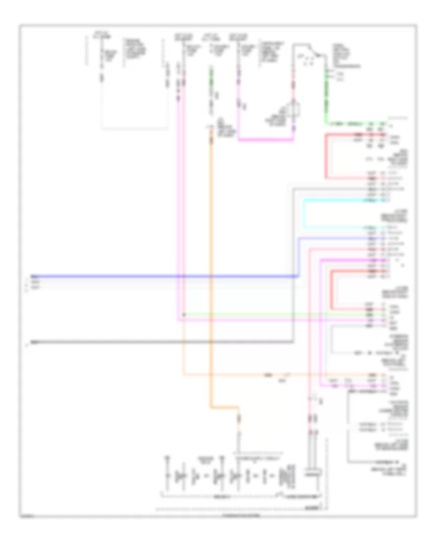
Anti-lock Brakes Wiring Diagram, Except Hybrid (2 of 2) for Toyota Highlander Hybrid 2011
List of elements for Anti-lock Brakes Wiring Diagram, Except Hybrid (2 of 2) for Toyota Highlander Hybrid 2011:
- (if equipped) control ind assist downhill
- +b(dome) or ig
- 2.7l
- 3.5l
- Abs ind
- B50
- B51
- Bat
- Bd1
- Buzzer
- Can if
- Canh
- Canl
- Combination meter
- D10
- D4 (behind left kick panel)
- D60
- D61
- Do3
- Drive ic
- Ecm (behind right side of dash)
- Ecu-b1 fuse 10a
- Ecu-ig 1 fuse 10a
- Ed1
- Ed3
- Engine room r/b (left side of engine compt)
- Ess
- F11
- G12
- Gauge 1 fuse 10a
- Gauge 2 fuse 7.5a
- Gnd
- H16
- Hot at all times
- Hot in on or start
- Ig2
- Ind brake
- Ind master
- Ind trac off
- Ind vsc off
- Instrument panel j/b (behind left end of dash)
- J/c b46 (behind right side of dash)
- J/c d55 (behind right side of dash)
- J/c d59 (behind right side of dash)
- J/c e23 (behind left side of dash)
- J/c o36 (behind left side of rear bumper)
- Micro computer
- N r
- O2 (behind left rear wheelwell)
- Od1
- Park/ neutral position switch (on transmission)
- Pnk
- Red
- Slip ind
- Steering sensor (in steering column)
- Yaw rate sensor (under center console)
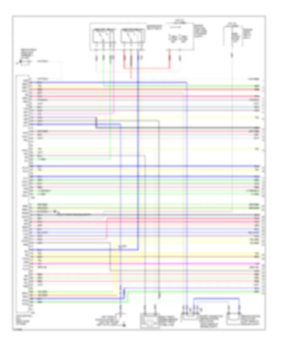
Anti-lock Brakes Wiring Diagram, Hybrid (1 of 4) for Toyota Highlander Hybrid 2011
List of elements for Anti-lock Brakes Wiring Diagram, Hybrid (1 of 4) for Toyota Highlander Hybrid 2011:
- (behind right headlight assembly) j/c a57
- +bi2
- +bi4
- A2 (right front engine compt)
- A45
- A46
- A55
- A56
- Abs 1 fuse 50a
- Abs 2 fuse 50a
- Abs main 2 fuse 10a
- Abs mtr 1 relay
- Abs mtr 2 relay
- Ad9
- Brake stroke simulator (left rear of engine compt)
- Bs01
- Bs02
- Bs03
- Cty
- Do2
- Engine room r/b (left side of engine compt)
- Engine room relay box 2
- Engine room relay box 3
- Fla+
- Fla-
- Flr+
- Flr-
- Fr+
- Fr-
- Fra+
- Fra-
- Frr+
- Frr-
- Gnd
- Gnd6
- Gs1
- Hot at all times
- Left front door courtesy light switch (left "b" pillar)
- Mr1
- Mr2
- Mtt
- Nca
- Pac1
- Pck1
- Pck2
- Pfl
- Pfr
- Pmc1
- Pmc2
- Pnk
- Prl
- Prr
- R1-
- R2-
- Red
- Right front speed sensor (right front wheel hub)
- Rla+
- Rla-
- Rlr+
- Rlr-
- Rr+
- Rr-
- Rra+
- Rra-
- Rrr+
- Rrr-
- Rss
- Sg1
- Sg2
- Sg3
- Short connector (brake stroke simulator) (right rear of engine compt)
- Skid control ecu (right side of dash)
- Smc1
- Smc2
- Stpo
- Vcm
- Vcm2
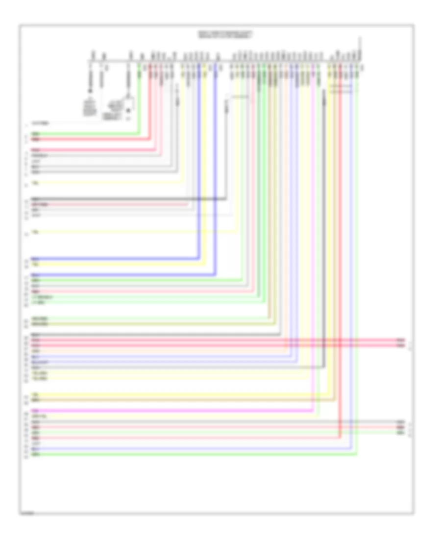
Anti-lock Brakes Wiring Diagram, Hybrid (2 of 4) for Toyota Highlander Hybrid 2011
List of elements for Anti-lock Brakes Wiring Diagram, Hybrid (2 of 4) for Toyota Highlander Hybrid 2011:
- (right side of engine compt) brake actuator assembly
- A1 (right front engine compt)
- A24
- A53
- A54
- Bm1
- Bm2
- Bs1
- Bs2
- Fla+
- Fla-
- Flr+
- Flr-
- Fra+
- Fra-
- Frr+
- Frr-
- Gnd1
- Gnd2
- J/c a57 (behind right headlight assembly)
- Mtt
- Nca
- Pac1
- Pck1
- Pck2
- Pfl
- Pfr
- Pmc1
- Pmc2
- Pnk
- Prl
- Prr
- Red
- Rla+
- Rla-
- Rlr+
- Rlr-
- Rra+
- Rra-
- Rrr+
- Rrr-
- Smc1
- Smc2
- Vcm
- Vcm2
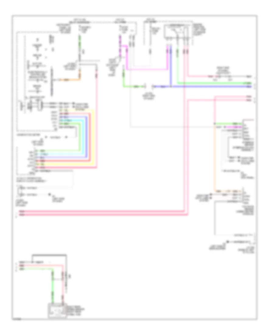
Anti-lock Brakes Wiring Diagram, Hybrid (3 of 4) for Toyota Highlander Hybrid 2011
List of elements for Anti-lock Brakes Wiring Diagram, Hybrid (3 of 4) for Toyota Highlander Hybrid 2011:
- (right end of dash) j/c a74 & d77
- +b(dome or ig)
- A74
- Abs ind
- An1
- Bat
- Brake ind
- Buzzer
- Can if
- Canh
- Canl
- Clk
- Combination meter
- Computer data lines system
- D10
- D4 (left kick panel)
- D77
- Data
- Do3
- Drive ic
- E1 (left side of dash)
- Ecu b 1 fuse 10a
- Ed3
- Electronically controlled brake system
- Engine room r/b (left side of engine compt)
- Ess
- G12
- Gauge 2 fuse 7.5a
- Gnd
- Hot at all times
- Hot w/ ig2 relay energized
- Hsi+
- Hsi-
- Ig+
- Ig2
- Instrument panel j/b (left side of dash)
- J/c a74 (right end of dash)
- J/c e23 (left side of dash)
- J/c o36 (base of left "d" pillar)
- Lcl+
- Lcl-
- Master ind
- Mclk
- Mdat
- Micro computer
- Nca
- O2 (left side of rear bumper)
- Pnk
- Red
- Right rear speed sensor (right rear wheel hub)
- Slip ind
- Steering sensor (steering column assembly)
- Stop fuse 10a
- Stop light switch (left side of dash)
- Stop relay
- Sync
- Traction off ind
- W/ multi information display clock assembly
- Yaw rate sensor (under center console)
Anti-lock Brakes Wiring Diagram, Hybrid (4 of 4) for Toyota Highlander Hybrid 2011
List of elements for Anti-lock Brakes Wiring Diagram, Hybrid (4 of 4) for Toyota Highlander Hybrid 2011:
- (behind right headlight assembly) j/c a57
- +bc
- +bi1
- +bi3
- A2 (right front engine compt)
- A44
- A47
- Abs main 1 fuse 10a
- Abs main 3 fuse 15a
- Ad4
- Ao2
- Brake fluid level warning switch (brake master cylinder reservoir assembly) (brake fluid reservoir)
- Brake pedal stroke sensor assembly
- Ca1h
- Ca1l
- Ca2h
- Ca2l
- Capaciter fuse 15a
- Cbi1
- Cbi2
- Computer data lines system
- Csw
- D3 (right center of dash)
- Do3
- Ecu ig 2 fuse 7.5a
- Ecu-ig 1 fuse 10a
- Ena
- Engine room r/b (left side of engine compt)
- Engine room relay box 3
- F11
- F19
- Fail
- Fl+
- Fl-
- Fss
- Gnd
- Gnd2
- Gnd3
- Gnd4
- Gnd5
- Gs2
- Hot at all times
- Hot w/ ig1 relay energized
- Hot w/ ig2 relay energized
- Ig1
- Ig2
- Ign fuse 10a
- Ill+
- Ill-
- Instrument panel j/b (left side of dash)
- J/c a57 (behind right headlight assembly)
- J/c a58 (left side of dash)
- Lbl
- Left front speed sensor (left front wheel hub)
- Left rear speed sensor (left rear wheel hub)
- Nca
- O3 (right side of rear bumper)
- Out1
- Out2
- Pnk
- Red
- Rl+
- Rl-
- Sgsk
- Skg
- Skid control buzzer (left side dash)
- Skid control ecu (right side of dash)
- Sks
- Sks1
- Sks2
- Stp
- Stp2
- System interior lights
- Vbz
- Vcsk
- Vsc off switch