ANTI-LOCK BRAKES
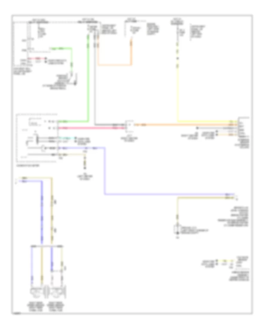
Anti-lock Brakes Wiring Diagram, Except Hybrid (1 of 2) for Toyota Highlander LE 2014

List of elements for Anti-lock Brakes Wiring Diagram, Except Hybrid (1 of 2) for Toyota Highlander LE 2014:
- (w/ dynamic radar cruise control & downhill assist control) stop lp relay
- +bs
- 2wd
- 4wd
- A70
- A71
- Abs 1 fuse 50a
- Abs 2 fuse 30a
- Ae (right front corner of engine compt)
- Af (right front corner of engine compt)
- Am1
- Brake actuator assembly (right rear of engine compt)
- Brake pedal load sensing switch (above brake pedal)
- Canh
- Canl
- Computer data lines system
- Cruise control system
- Csw
- Downhill assist control
- Downhill assist control switch (if equipped)
- Engine room r/b 1 (left side of engine compt)
- F12
- F15
- F16
- Fa2
- Fb (under front of center console)
- Fl+
- Fl-
- Fr+
- Fr-
- Fsw+
- Gnd1
- Gnd2
- Ground j/c 2 (left front corner of engine compt)
- Hdcs
- Hot at all times
- Hot w/ ig1 3 relay energized
- Ig1
- Ig1 2 fuse 7.5a
- Instrument panel j/b (behind left end of dash)
- Interior lights system
- J/c 1 (left side of dash)
- Left front speed sensor (left front wheel hub)
- Left rear speed sensor (left rear wheel hub)
- Om1
- Or1
- Red
- Right front speed sensor (right front wheel hub)
- Rl+
- Rl-
- Rr+
- Rr-
- Sp1
- Stop fuse 10a
- Stop light switch assembly (above brake pedal)
- Stp
- Stp2
- Stpo
- Vsc off switch
- W/ dynamic radar cruise control &
- W/o dynamic radar cruise control & downhill assist control
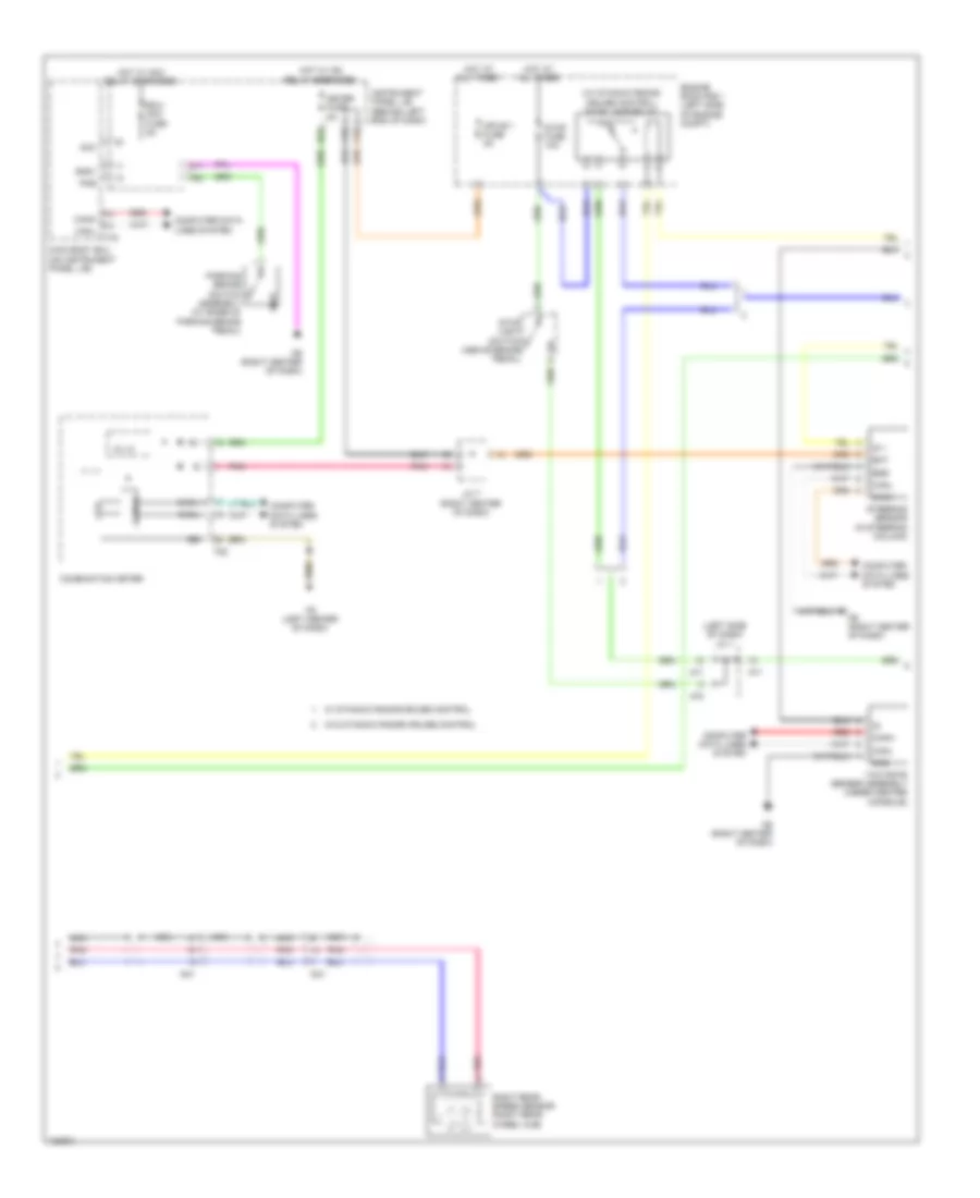
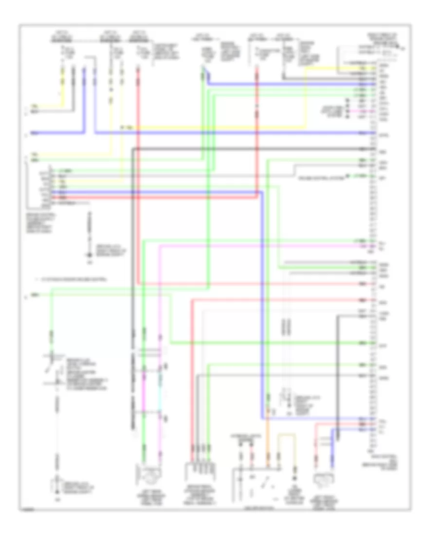
Anti-lock Brakes Wiring Diagram, Except Hybrid (2 of 2) for Toyota Highlander LE 2014
List of elements for Anti-lock Brakes Wiring Diagram, Except Hybrid (2 of 2) for Toyota Highlander LE 2014:
- 2wd
- 4wd
- 5v ic
- A48
- A51
- A53
- Acc
- Airbag sensor assembly (under front of center console)
- Am1
- B/le
- Bat
- Brake fluid level warning switch (brake master cylinder reservoir sub-assembly) (on brake master cylinder reservoir)
- Can if
- Canh
- Canl
- Combination meter
- Computer data lines system
- Cpu
- Ecu- acc fuse 5a
- Engine room r/b 1 (left side of engine compt)
- Ess
- F19
- F22
- F28
- F32
- F38
- Fa2
- Fd (left center of dash)
- Fe (right center of dash)
- Ground j/c 2 (left front corner of engine compt)
- Hot at all times
- Hot w/ acc relay energized
- Hot w/ ig1 3 relay energized
- Hot w/ ig2 relay energized
- I/f
- Ig 1
- Ig+
- Ig1 3 fuse 10a
- Instrument panel j/b (behind left end of dash)
- J/c 7 (right center of dash)
- Main body ecu (on instrument panel j/b)
- Meter fuse 5a
- Mpx-b 1 fuse 5a
- Om1
- Oo1
- Parking brake switch assembly (at base of parking brake pedal)
- Pkb
- Pnk
- Red
- Right rear speed sensor (right rear wheel hub)
- Steering sensor (in steering column)
- Yaw rate sensor
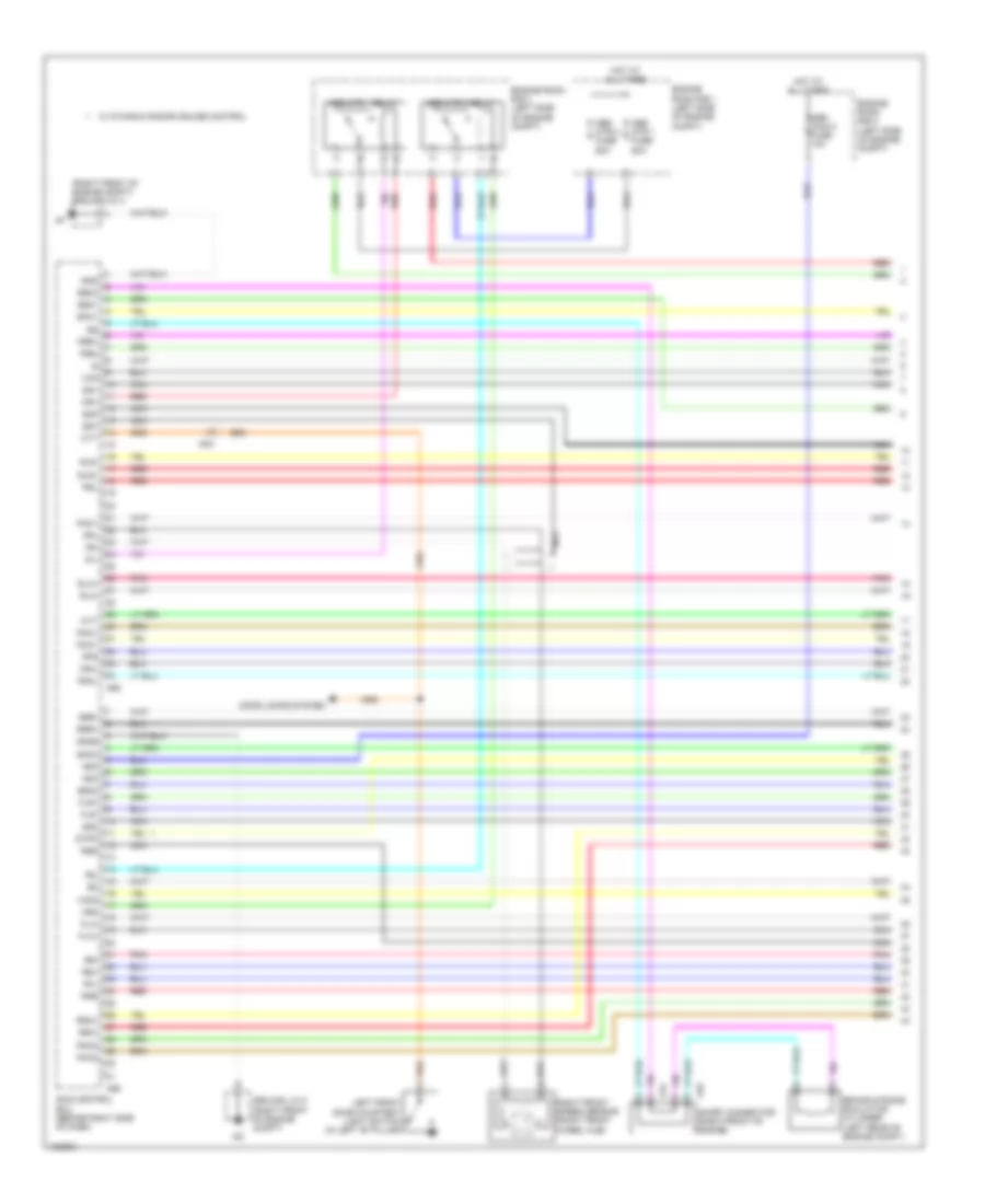
Anti-lock Brakes Wiring Diagram, Hybrid (1 of 4) for Toyota Highlander LE 2014
List of elements for Anti-lock Brakes Wiring Diagram, Hybrid (1 of 4) for Toyota Highlander LE 2014:
- (right front of engine compt) ground j/c 4
- +bi2
- +bi4
- A44
- A45
- A62
- A65
- Abs main 2 fuse 10a
- Abs mtr 1 fuse 50a
- Abs mtr 1 relay
- Abs mtr 2 fuse 50a
- Abs mtr 2 relay
- Am3
- Brake stroke simulator cylinder (left rear of engine compt)
- Bs01
- Bs02
- Bs03
- Cty
- Door locks system
- Engine room r/b 1 (left side of engine compt)
- Engine room r/b 3 (left side of engine compt)
- Fla+
- Fla-
- Flr+
- Flr-
- Fr+
- Fr-
- Fra+
- Fra-
- Frr+
- Frr-
- Gnd
- Gnd6
- Ground j/c 5 (right front of engine compt)
- Gs1
- Hot at all times
- Left front door courtesy light switch (in left "b" pillar)
- Mr1
- Mr2
- Mtt
- Nca
- Pac1
- Pck1
- Pck2
- Pfl
- Pfr
- Pmc1
- Pmc2
- Pnk
- Prl
- Prr
- R1-
- R2-
- Red
- Right front speed sensor (right front wheel hub)
- Rla+
- Rla-
- Rlr+
- Rlr-
- Rr+
- Rr-
- Rra+
- Rra-
- Rrr+
- Rrr-
- Rss
- Sg1
- Sg2
- Sg3
- Short connector (right front of engine)
- Skid control ecu (behind right side of dash)
- Smc1
- Smc2
- Stpo
- Vcm
- Vcm2
- W/ dynamic radar cruise control
Anti-lock Brakes Wiring Diagram, Hybrid (2 of 4) for Toyota Highlander LE 2014
List of elements for Anti-lock Brakes Wiring Diagram, Hybrid (2 of 4) for Toyota Highlander LE 2014:
- A48
- A49
- A50
- Ae (right front corner of engine compt)
- Ag (right front corner of engine compt)
- Bm1
- Bm2
- Brake actuator assembly (right rear of engine compt)
- Gnd1
- Gnd2
- Mtt
- Nca
- Pck1
- Pck2
- Pnk
- Red
- W/ dynamic radar cruise control
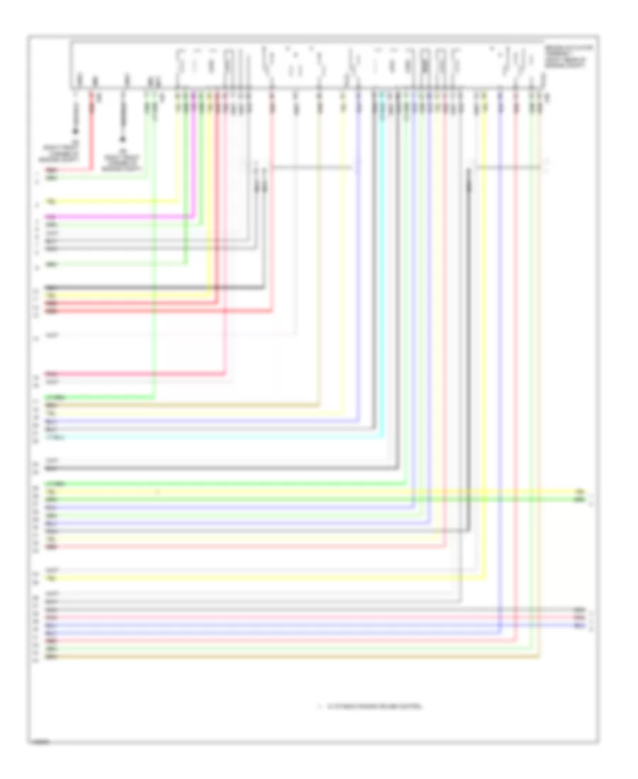
Anti-lock Brakes Wiring Diagram, Hybrid (3 of 4) for Toyota Highlander LE 2014
List of elements for Anti-lock Brakes Wiring Diagram, Hybrid (3 of 4) for Toyota Highlander LE 2014:
- (left side of dash) j/c 1
- (w/ dynamic radar cruise control) stop lamp relay
- 5v ic
- A48
- A53
- A70
- A71
- Acc
- Am1
- Bat
- Can if
- Canh
- Canl
- Combination meter
- Computer data lines system
- Cpu
- D11
- Ecu- acc fuse 5a
- Engine room r/b 1 (left side of engine compt)
- Ess
- F19
- F22
- F28
- F32
- Fd (left center of dash)
- Fe (right center of dash)
- Gnd
- Gnd1
- Hot at all times
- Hot w/ acc relay energized
- Hot w/ ig2 relay energized
- Ig 1
- Ig+
- Instrument panel j/b (behind left end of dash)
- J/c 7 (right center of dash)
- Main body ecu (on instrument panel j/b)
- Meter fuse 5a
- Mpx-b 1 fuse 5a
- Nca
- Om1
- Parking brake switch assembly (at base of parking brake pedal)
- Pkb
- Pnk
- Red
- Right rear speed sensor (right rear wheel hub)
- Steering sensor (in steering column)
- Stop fuse 10a
- Stop light switch (above brake pedal)
- W/ dynamic radar cruise control
- W/o dynamic radar cruise control
- Yaw rate sensor assembly (under center console)
Anti-lock Brakes Wiring Diagram, Hybrid (4 of 4) for Toyota Highlander LE 2014
List of elements for Anti-lock Brakes Wiring Diagram, Hybrid (4 of 4) for Toyota Highlander LE 2014:
- (left side of engine compt)
- (right front of engine compt) ground j/c 4
- +bc
- +bi1
- +bi3
- A43
- A51
- A63
- A64
- Abs main 1 fuse 10a
- Abs main 3 fuse 10a
- Am1
- Brake fluid level warning switch (brake master cylinder reservoir assembly) (on brake master cylinder reservoir)
- Brake pedal stroke sensor assembly (top of brake pedal assembly)
- Ca1h
- Ca1l
- Ca2h
- Ca2l
- Capacitor fuse 10a
- Cbi1
- Cbi2
- Computer data lines system
- Cruise control system
- Csw
- Ena
- Engine room r/b 1 (left side of engine compt)
- Engine room r/b 3
- F12
- F15
- F20
- Fa2
- Fail
- Fb (under front of center console)
- Fl+
- Fl-
- Fss
- Gnd
- Gnd2
- Gnd3
- Gnd4
- Gnd5
- Ground j/c 5 (right front of engine compt)
- Gs2
- Hot at all times
- Hot w/ ig1 3 relay energized
- Hot w/ ig2 relay energized
- Ig 2 fuse 7.5a
- Ig1
- Ig1 2 fuse 7.5a
- Ig1 3 fuse 10a
- Ig2
- Instrument panel j/b (behind left end of dash)
- Interior lights system
- Lbl
- Left front speed sensor (left front wheel hub)
- Left rear speed sensor (left rear wheel hub)
- Nca
- Om1
- Out1
- Out2
- Red
- Rl+
- Rl-
- Skg
- Skid control ecu (behind right side of dash)
- Sks
- Sks1
- Sks2
- Sp1
- Stp
- Stp2
- Vcsk
- Vsc off switch
- W/ dynamic radar cruise control