ANTI-LOCK BRAKES
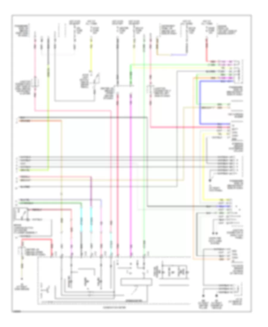
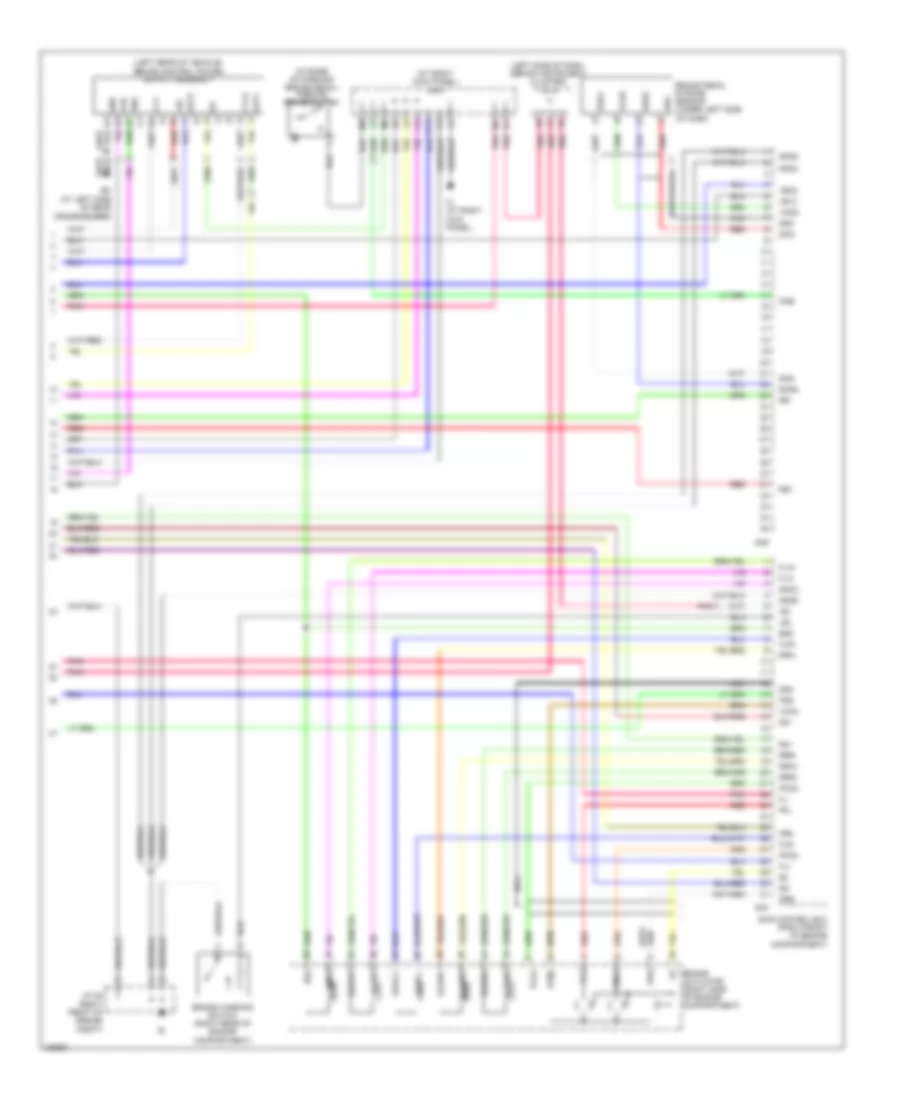
Anti-lock Brakes Wiring Diagram, Except Hybrid (1 of 2) for Toyota Highlander Sport 2006

List of elements for Anti-lock Brakes Wiring Diagram, Except Hybrid (1 of 2) for Toyota Highlander Sport 2006:
- (above brake pedal) brake pedal load sensing switch
- (at right dash brace) ib
- (behind right side of dash) engine control module
- (below left side of dash) pressure switch
- (under left headlight) eh
- +bs
- Abs 1 fuse 30a
- Abs 2 fuse 50a
- Abs cut relay
- Abs mtr relay
- Abs r/b (on left rear of engine compt)
- Brl
- Canh
- Canl
- Center j/b (behind upper center of dash)
- Computer data lines system
- Csw
- D/g
- Ea (at right front fender apron)
- Eng+
- Eng-
- F13
- Fl+
- Fl-
- Fr+
- Fr-
- Fsw+
- Fusible link block (on left side of engine compt)
- Gnd1
- Gnd2
- Hot at all times
- Ig1
- Init
- Junction connector 4 (on right side of engine compartment)
- Left front abs speed sensor (at left front wheel)
- Left rear abs speed sensor (on left rear wheel)
- Mrf
- Neo
- Parking brake switch (at base of parking brake pedal)
- Passenger side j/b (behind right side of dash)
- Pkb
- Pnk
- Red
- Right front abs speed sensor (at right front wheel)
- Right rear abs speed sensor (on right rear wheel)
- Rl+
- Rl-
- Rr+
- Rr-
- Skid control ecu with actuator (right front of engine compt)
- Sp1
- Stp
- Trac off switch (2wd)
- Trc+
- Trc-
- Vscw
- Wfse
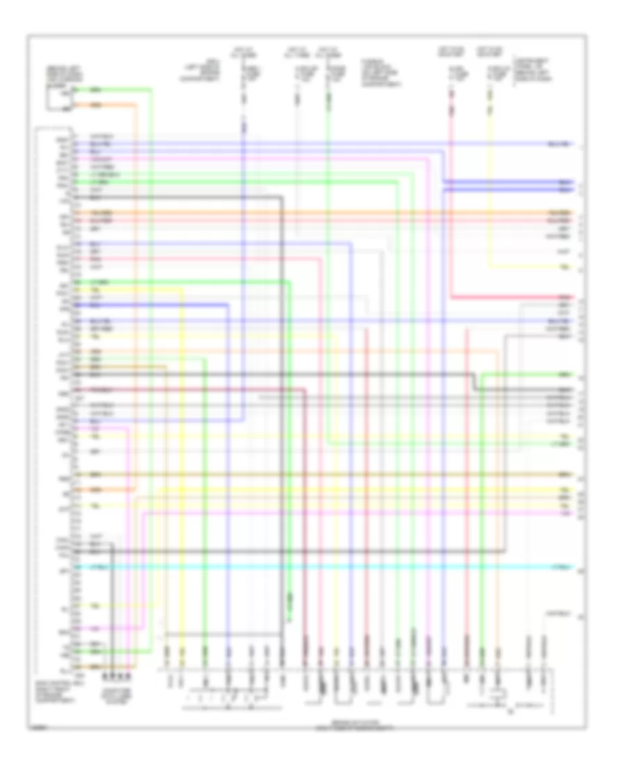
Anti-lock Brakes Wiring Diagram, Except Hybrid (2 of 2) for Toyota Highlander Sport 2006
List of elements for Anti-lock Brakes Wiring Diagram, Except Hybrid (2 of 2) for Toyota Highlander Sport 2006:
- A11
- Abs ind
- B12
- Batt
- Bb (at right center pillar)
- Bf (at right corner of vehicle)
- Brake ind
- Brake warning switch (on master cylinder assembly)
- C11
- C12
- Canh
- Canl
- Center j/b (behind upper center of dash)
- Combination meter
- Computer data lines system
- D10
- D11
- Dome fuse 10a
- Ecu-b fuse 7.5a
- Ecu-ig fuse 10a
- Engine room j/b (on left side of engine compt)
- Ess
- G10
- Gnd
- Heater fuse 10a
- Hot at all times
- Hot in on or start
- Ib (at right dash brace)
- Ic (at right kick panel)
- Ign fuse 10a
- Ind (2wd)
- Instrument panel j/b (behind left side of dash)
- J/c 19 (at rear of vehicle)
- Junction connector 16 (right kick panel)
- Junction connector 17 (behind left side of dash)
- Junction connector 6 (left side of dash, behind instrument cluster)
- K13
- Passenger side j/b (behind right side of dash)
- Pnk
- Red
- Slip ind
- Speedometer
- Steering sensor (in steering column)
- Stop fuse 20a
- Stop light switch (above brake pedal)
- Tire air pressure ind
- Trac off
- Vsc ind
- Vsc warning buzzer
- Yaw rate sensor (on rear of vehicle)
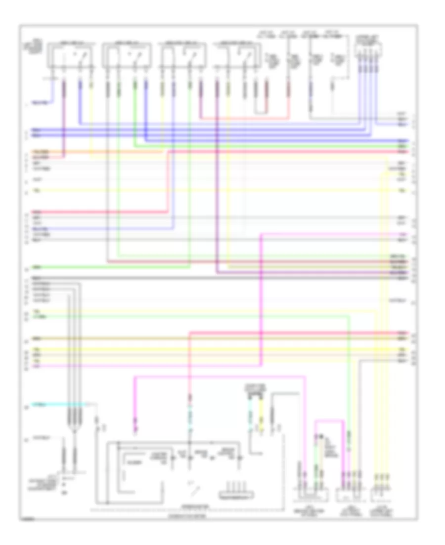
Anti-lock Brakes Wiring Diagram, Hybrid (1 of 4) for Toyota Highlander Sport 2006
List of elements for Anti-lock Brakes Wiring Diagram, Hybrid (1 of 4) for Toyota Highlander Sport 2006:
- (behind left side of dash) vsc warning buzzer
- (behind left side of dash)
- +b11
- +bo1
- Abs 1 fuse 10a
- Bm1
- Bm2
- Brake actuator (right side of engine compt)
- Bs1
- Canh
- Canl
- Computer data lines system
- Cty+
- D10
- Dome fuse 10a
- Ecu-b1 fuse 10a
- Ecu-ig fuse 10a
- Ena
- Fail
- Fr+
- Fr-
- Fra+
- Fra-
- Frr+
- Frr-
- Fusible link block (on left side of engine compartment)
- Gnd1
- Gnd2
- Gnd3
- Hot at all times
- Hot in on or start
- Ig1
- Ign fuse 10a
- Instrument panel j/b
- Mr1
- Mtt
- Pac1
- Pck1
- Per
- Pfr
- Pmc1
- Pnk
- Prl
- R/b 4 (left side of engine compartment)
- R1+
- R1-
- R3+
- Rl+
- Rl-
- Rla+
- Rla-
- Rlr+
- Rss
- S37
- S38
- Sg1
- Skid control ecu (right front of engine compartment)
- Slafr+
- Slafr-
- Slarl+
- Slarl-
- Slrfr+
- Slrfr-
- Slrrl+
- Slrrl-
- Smc1
- Sp1
- Stp
- Vbz
- Vcm
- Vcm1
- Wfse
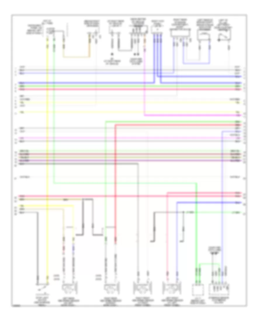
Anti-lock Brakes Wiring Diagram, Hybrid (2 of 4) for Toyota Highlander Sport 2006
List of elements for Anti-lock Brakes Wiring Diagram, Hybrid (2 of 4) for Toyota Highlander Sport 2006:
- (upper left kick panel) j/c 26
- Abs 1 relay
- Abs 2 fuse 10a
- Abs 2 relay
- Abs 3 fuse 15a
- Abs mtr 1 fuse 30a
- Abs mtr 1 relay
- Abs mtr 2 fuse 30a
- Abs mtr 2 relay
- B12
- Brake control ind
- Brake ind
- Buzzer
- C11
- C12
- Combination meter
- Computer data lines system
- D11
- Hot at all times
- Ib (at right dash brace)
- J/b 3 (behind center of dash)
- J/b 4 (at right kick panel)
- J/c 26 (upper left kick panel)
- J/c 4 (on right side of engine compartment)
- L11
- Master warning ind
- Multi display
- Pnk
- R/b 4 (left side of engine compt)
- Slip ind
- Speedometer
Anti-lock Brakes Wiring Diagram, Hybrid (3 of 4) for Toyota Highlander Sport 2006
List of elements for Anti-lock Brakes Wiring Diagram, Hybrid (3 of 4) for Toyota Highlander Sport 2006:
- (2wd)
- (4wd)
- (at right rear of vehicle) j/c 19
- (behind left side of dash)
- (behind right side of dash) j/c 31 & 32
- (left "b" pillar) left front door courtesy switch
- (left rear of engine compt) brake stroke simulator cylinder
- (near center of vehicle) yaw rate sensor
- (or red)
- (right kick panel) j/c 16
- (right rear of engine compartment) short connector 35 & 36
- Bat
- Bf (at right rear of vehicle)
- Canh
- Canl
- Computer data lines system
- G10
- Gnd
- Hot at all times
- Instrument panel j/b
- J/c 17 (behind left side of dash)
- J31
- J32
- Left front abs speed sensor (at left front wheel)
- Left rear abs speed sensor (on left rear wheel)
- Nca
- Pnk
- Red
- Right front abs speed sensor (at right front wheel)
- Right rear abs speed sensor (on right rear wheel)
- S35
- S36
- Steering sensor (in steering column)
- Stop fuse 20a
- Stop light switch (above brake pedal)
Anti-lock Brakes Wiring Diagram, Hybrid (4 of 4) for Toyota Highlander Sport 2006
List of elements for Anti-lock Brakes Wiring Diagram, Hybrid (4 of 4) for Toyota Highlander Sport 2006:
- (at base of parking brake pedal) parking brake switch
- (at right kick panel) j/b 4
- (left side of dash, behind instrument cluster) j/c 6
- +b12
- +bc
- +bo2
- Bc (at left side of rear crossmember)
- Brake actuator (right side of engine compartment)
- Brake pedal stroke sensor (under left side of dash)
- Brake warning switch (right rear of engine compartment)
- Bs2
- C11
- Cty
- Cty2
- Ena
- Fail
- Fl+
- Fl-
- Fla+
- Fla-
- Flr+
- Flr-
- Fss
- Gnd
- Gnd4
- Gnd5
- Gnd6
- Ic (at right kick panel)
- Ig1
- Ig2
- J/c 25 (right front of engine compt)
- Lbl
- Mr2
- Nca
- Out1
- Out2
- Pck2
- Pfl
- Pkb
- Pmc2
- Pnk
- Prr
- R2+
- R2-
- R4+
- Red
- Rr+
- Rr-
- Rra+
- Rra-
- Rrr+
- Rrr-
- S39
- S40
- Sg2
- Skg
- Skid control ecu (right front of engine compartment)
- Sks
- Sks1
- Sks2
- Slafl+
- Slafl-
- Slarr+
- Slarr-
- Slrfl+
- Slrfl-
- Slrrr+
- Slrrr-
- Smc2
- Ssk
- Vcm2
- Vcsk