ANTI-LOCK BRAKES
Anti-lock Brakes Wiring Diagram (1 of 5) for Toyota Prius 2008

List of elements for Anti-lock Brakes Wiring Diagram (1 of 5) for Toyota Prius 2008:
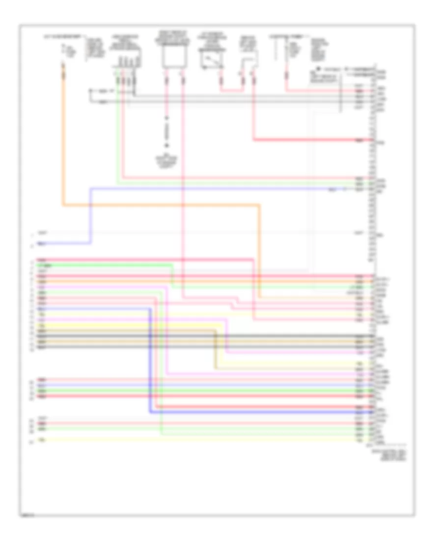
Anti-lock Brakes Wiring Diagram (2 of 5) for Toyota Prius 2008
List of elements for Anti-lock Brakes Wiring Diagram (2 of 5) for Toyota Prius 2008:
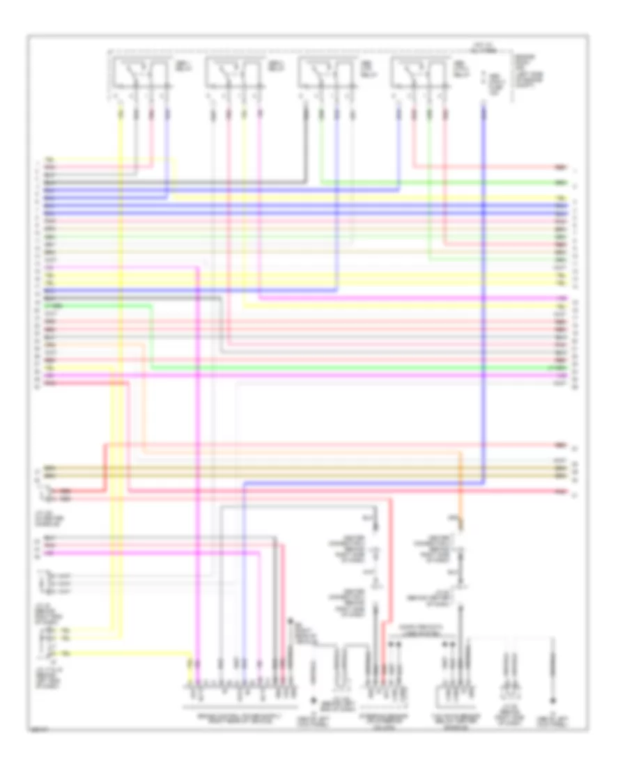
Anti-lock Brakes Wiring Diagram (3 of 5) for Toyota Prius 2008
List of elements for Anti-lock Brakes Wiring Diagram (3 of 5) for Toyota Prius 2008:
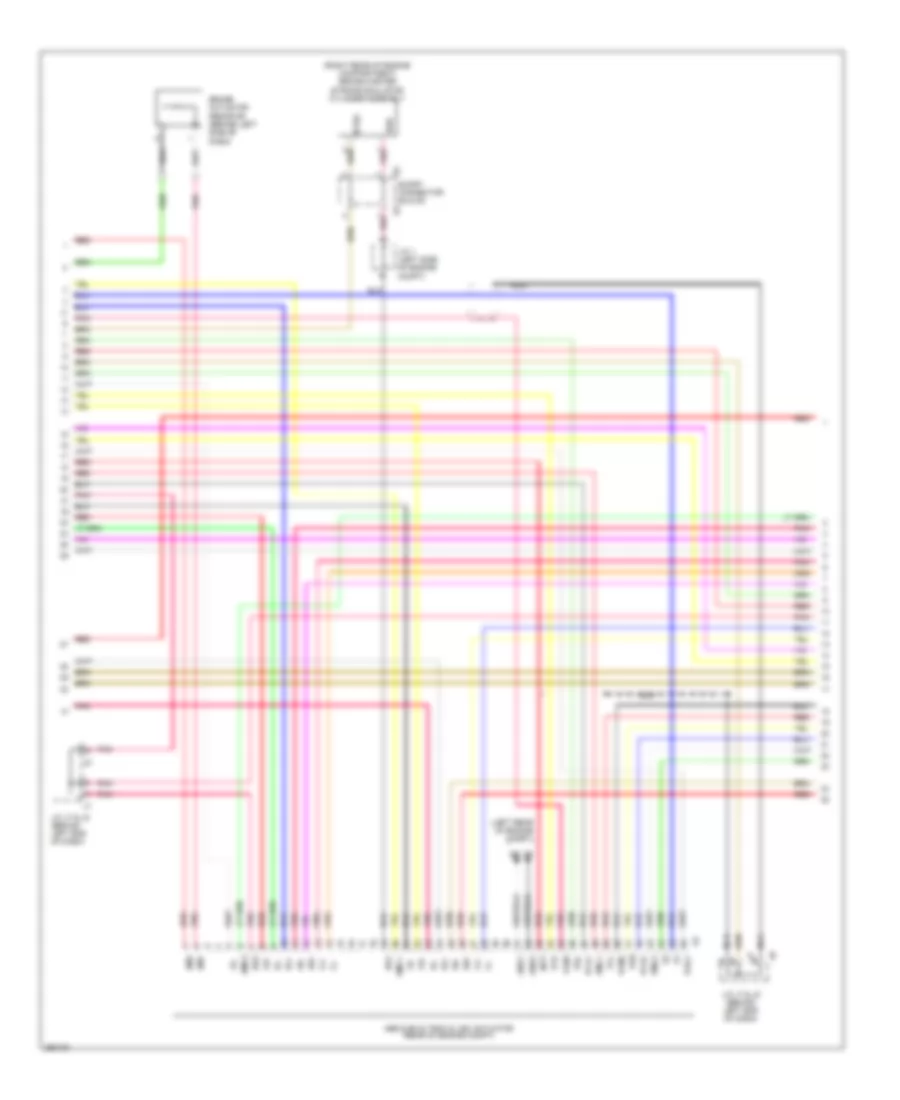
Anti-lock Brakes Wiring Diagram (4 of 5) for Toyota Prius 2008
List of elements for Anti-lock Brakes Wiring Diagram (4 of 5) for Toyota Prius 2008:
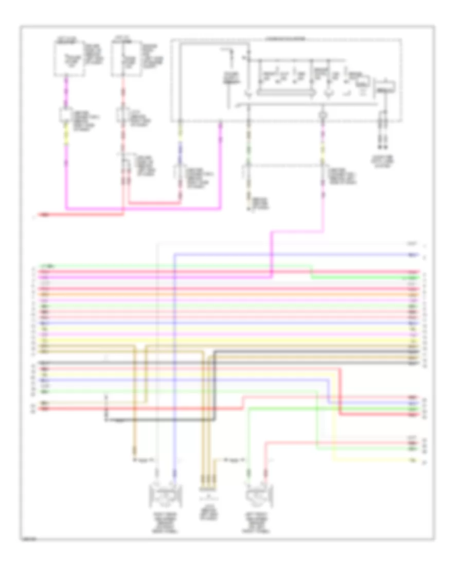
Anti-lock Brakes Wiring Diagram (5 of 5) for Toyota Prius 2008
List of elements for Anti-lock Brakes Wiring Diagram (5 of 5) for Toyota Prius 2008: