ANTI-LOCK BRAKES
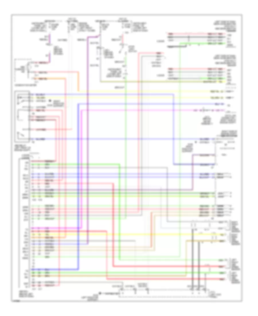
Anti-lock Brake Wiring Diagrams for Toyota RAV4 1998
List of elements for Anti-lock Brake Wiring Diagrams for Toyota RAV4 1998:
- (left side of dash, near accelerator) (4wd only) abs deceleration sensor
- (or nca)
- (right radiator support)
- (right side of engine compt) abs actuator
- +ig
- 10a
- 2 door
- 4 door
- A16
- A17
- Abs ecu (behind left side of dash)
- Abs fuse 50a
- Abs relay (left front of engine compt)
- Abs warning ind
- B13
- C11
- C18
- Combination meter
- Data link connector 1 (right side of engine compt)
- Ecu-ig fuse 10a
- Engine room r/b (left front strut tower)
- Fl+
- Fl-
- Fr+
- Fr-
- G108 (left radiator support)
- G109
- G109 (right radiator support)
- Gauge fuse 10a
- Ggnd
- Gl1
- Gl2
- Gnd
- Gs2
- Gsi
- Gst
- Hot at all times
- Hot in on
- Ig1
- Instrument panel j/b (lower left side of dash)
- J/b 3 (behind center of dash)
- J/c 2 (left kick panel)
- J/c 4 (behind meter assembly)
- Left front abs speed sensor
- Left rear abs speed sensor
- Nca
- Red
- Right front abs speed sensor
- Right rear abs speed sensor
- Rl+
- Rl-
- Rr+
- Rr-
- Sflh
- Sflr
- Sfrh
- Sfrr
- Srlh
- Srlr
- Srrh
- Srrr
- Stop fuse
- Stop- light switch
- Stp
- Vgs
 English