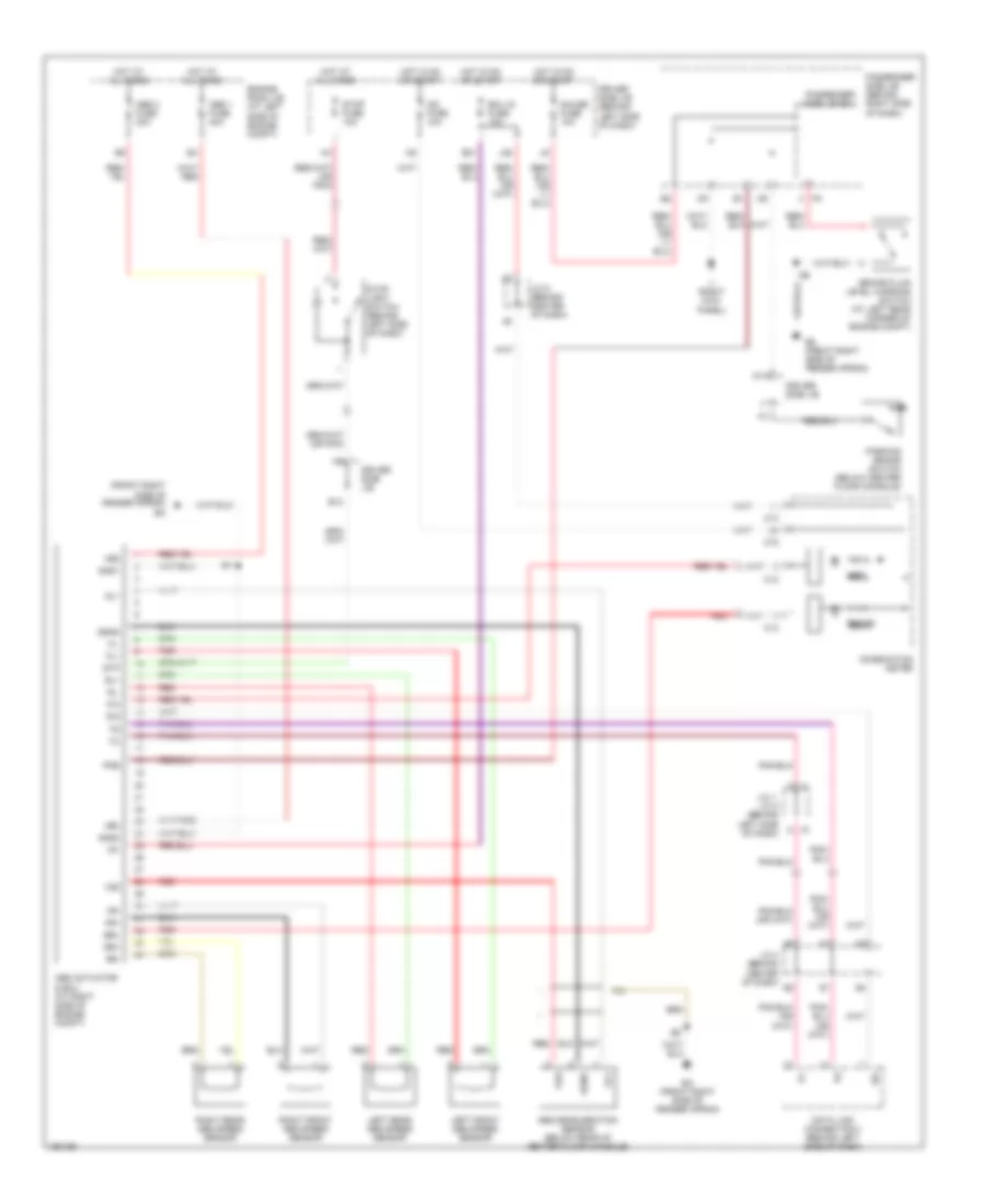
ANTI-LOCK BRAKES
Anti-lock Brake Wiring Diagrams for Toyota RAV4 L 2002
List of elements for Anti-lock Brake Wiring Diagrams for Toyota RAV4 L 2002:
- (front right side of fender apron) ea
- +bm
- +bs
- Abs
- Abs 1 fuse 40a
- Abs 2 fuse 30a
- Abs actuator & ecu (at right side of engine compt)
- Abs deceleration sensor (below rear of center floor console)
- Brake
- Brake fluid level warning switch (at left rear corner of engine compt)
- Brl
- C j1
- C12
- C13
- C15
- Combination meter
- D/g
- Data link connector 3 (behind left side of dash)
- Driver side j/b
- Driver side j/b (behind left side of dash)
- E12
- E21
- Ea (front right side of fender apron)
- Ecu ig fuse 10a
- Engine room j/b (at left side of engine compt)
- Fl+
- Fl-
- Fr+
- Fr-
- Gauge fuse 10a
- Ggnd
- Gl1
- Gnd1
- Gnd2
- Hot at all times
- Hot in on or start
- Ig1
- Ig2 fuse 10a
- Ii (right kick panel)
- J/c 1, j/c 2 (behind left side of dash)
- J/c 4 (behind center of dash)
- J/c 5 (behind center of dash)
- J2 a
- J28
- Left front abs speed sensor
- Left rear abs speed sensor
- M11
- Parking brake switch (below center floor console)
- Passenger side j/b (behind right side of dash)
- Passenger side j/b ecu
- Pkb
- Red
- Right front abs speed sensor
- Right rear abs speed sensor
- Rl+
- Rl-
- Rr+
- Rr-
- Sil
- Stop fuse 10a
- Stop light switch (behind left side of dash)
- Stp
- Vg5
- Vgs
 English