ANTI-LOCK BRAKES
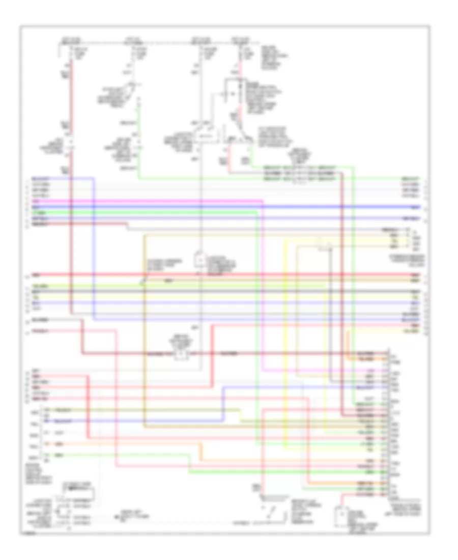
Anti-lock Brakes Wiring Diagram, with VSC (1 of 3) for Toyota Sienna CE 2003

List of elements for Anti-lock Brakes Wiring Diagram, with VSC (1 of 3) for Toyota Sienna CE 2003:
- (at right dash brace) ih
- Abs 2 fuse 25a
- Abs 3 fuse 25a
- Abs 4 fuse 5a
- Abs fuse 60a
- Abs ind
- Abs mtr relay
- Abs sol relay
- Brake ind
- Buzzer
- C10
- C11
- Combination meter
- Data link connector 1 (on right rear of engine compt)
- Data link connector 3 (below dash, right of steering column)
- Ea (at front of right inner fender panel)
- Ebdw
- Ed (near left strut tower)
- Engine room j/b 2 (on left side of engine compt)
- Fss
- Gnd2
- Gyaw
- Hot at all times
- I2 (in dash harness, at right side of dash)
- Ind
- J10
- Junction connector 17 (behind upper right side of dash)
- Junction connector 18 (on underside of steering column)
- Lbl
- Master cylinder pressure sensor (on master cylinder, on left rear of engine compartment)
- Nca
- Pkb
- Pmc
- R/b 7 (on left front of engine compartment)
- R/b 8 (on right rear of engine compt)
- Red
- Sil
- Slip ind
- Sp1
- Speedometer
- Ss1
- Ss2
- Trac off ind
- Vcm
- Vsc buzzer (inside steering column)
- Vsc ecu (behind upper left side of dash)
- Vsc ind
- Vscw
- Yaw
- Ygnd
- Yiga
Anti-lock Brakes Wiring Diagram, with VSC (2 of 3) for Toyota Sienna CE 2003
List of elements for Anti-lock Brakes Wiring Diagram, with VSC (2 of 3) for Toyota Sienna CE 2003:
- (at right side of firewall) ij
- (behind instrument cluster) j/b 3
- (in dash harness, at right side of dash)
- (near left strut tower) ed
- A/t indicator light switch (park/neutral position switch) (on transaxle)
- A11
- A17
- A18
- B13
- B17
- B18
- Brake fluid level warning switch (on brake fluid reservoir)
- Brl
- Ccs
- Cig fuse 15a
- Cruise control ecu (behind upper left center of dash)
- D13
- Diode (park/neutral
- Driver side j/b 1 (behind dash, left of steering column)
- Ecu-ig fuse 15a
- Eng+
- Eng-
- Engine control module (behind right side of dash)
- Ess
- Gauge fuse 10a
- Gnd
- Hot at all times
- Hot in on or acc
- Hot in on or start
- Ig1
- J/b 3 (behind instrument cluster)
- Junction connector 17 (behind upper right side of dash)
- Junction connector 18 (on underside of steering column)
- Junction connectors 2 & 3 (behind left side of instrument cluster)
- Lbl
- Lvl2
- Nca
- Neo
- Pkb
- Pkb2
- Pnk
- Position switch) (w/ door lock control) (behind upper left center of dash)
- Red
- Rss
- Ss1
- Ss2
- Steering sensor (inside steering column)
- Stop fuse 15a
- Stoplight switch (on bracket, above brake pedal)
- Translate ecu (behind upper left side of dash)
- Trc+
- Trc-
- Vsc+
- Vsc-
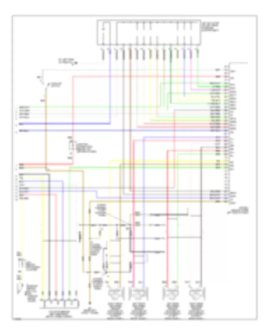
Anti-lock Brakes Wiring Diagram, with VSC (3 of 3) for Toyota Sienna CE 2003
List of elements for Anti-lock Brakes Wiring Diagram, with VSC (3 of 3) for Toyota Sienna CE 2003:
- (at left side of firewall) ig
- (in body harness, in left quarter- panel)
- (in dash harness, at right side of dash)
- Batt
- Csw
- D/g
- Ed (near left strut tower)
- Fl+
- Fl-
- Fr+
- Fr-
- Gl1
- Gnd1
- Gnda
- Gyw2
- Ig1
- Iga
- J/b 3 (behind instrument cluster)
- Junction connector 6 (behind top center of dash)
- Left front abs speed sensor (mounted on hub assembly of left front wheel)
- Left rear abs speed sensor (mounted on hub assembly of left rear wheel)
- Nca
- Parking brake switch (on parking brake lever)
- Pnk
- Red
- Right front abs speed sensor (mounted on hub assembly of right front wheel)
- Right rear abs speed sensor (mounted on hub assembly of right rear wheel)
- Rl+
- Rl-
- Rr+
- Rr-
- Sflh
- Sflr
- Sfrh
- Sfrr
- Smc1
- Smc2
- Src1
- Src2
- Srlh
- Srlr
- Srrh
- Srrr
- Stp
- Trac off switch
- Vsc actuator (on left rear of engine compartment)
- Vsc ecu (behind upper left side of dash)
- Yaw rate sensor (between front seats, under carpet)
- Yaw2
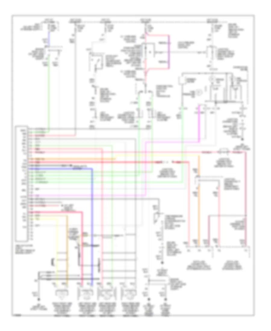
Anti-lock Brakes Wiring Diagram, without VSC for Toyota Sienna CE 2003
List of elements for Anti-lock Brakes Wiring Diagram, without VSC for Toyota Sienna CE 2003:
- (at left side of firewall) ig
- (in body harness, in left quarter- panel)
- +bm
- +bs
- A11
- Abs actuator & ecu (on left rear of engine compt)
- Abs fuse 60a
- Abs warning ind
- B j3
- B13
- B17
- B18
- Brake ind
- Brl
- C10
- C11
- Cig fuse 15a
- Combination meter
- D/g
- Data link connector 1 (on right rear of engine compt)
- Data link connector 3 (below dash, right of steering column)
- Diode (park/neutral position switch) (w/ wireless door lock control) (behind upper left center of dash)
- Driver side j/b 1 (behind dash, left of steering column)
- Ea (at front of right inner fender panel)
- Ecu-ig fuse 15a
- Ed (near left strut tower)
- Ee (at front of left inner fender panel)
- Engine room j/b 2 (on left side of engine compt)
- Fl+
- Fl-
- Fr+
- Fr-
- Gauge fuse 10a
- Gnd1
- Gnd2
- Headlights system
- Hot at all times
- Hot in on or acc
- Hot in on or start
- I2 (in dash harness, at right side of dash)
- Ig1
- Ij (at right side of firewall)
- Init
- J/b 3 (behind instrument cluster)
- J10
- J2 b
- Junction connector 17 (behind upper right side of dash)
- Junction connector 6 (behind top center of dash)
- Junction connectors 2 & 3 (behind left side of instrument cluster)
- Left front abs speed sensor (mounted on hub assembly of left front wheel)
- Left rear abs speed sensor (mounted on hub assembly of left rear wheel)
- Nca
- Park/neutral position switch (on transaxle)
- Pkb
- Pnk
- R/b 7 (on left front of engine compt)
- Red
- Right front abs speed sensor (mounted on hub assembly of right front wheel)
- Right rear abs speed sensor (mounted on hub assembly of right rear wheel)
- Rl+
- Rl-
- Rr+
- Rr-
- Sil
- Speedo- meter
- Spo
- Stop fuse 15a
- Stoplight switch (on bracket, above brake pedal)
- Stp
- Tire pressure ind
- Tire pressure warning standardization switch (on left side of dash)
- W/ wireless door lock control
- W/o wireless door lock control
- Wtir