ANTI-LOCK BRAKES
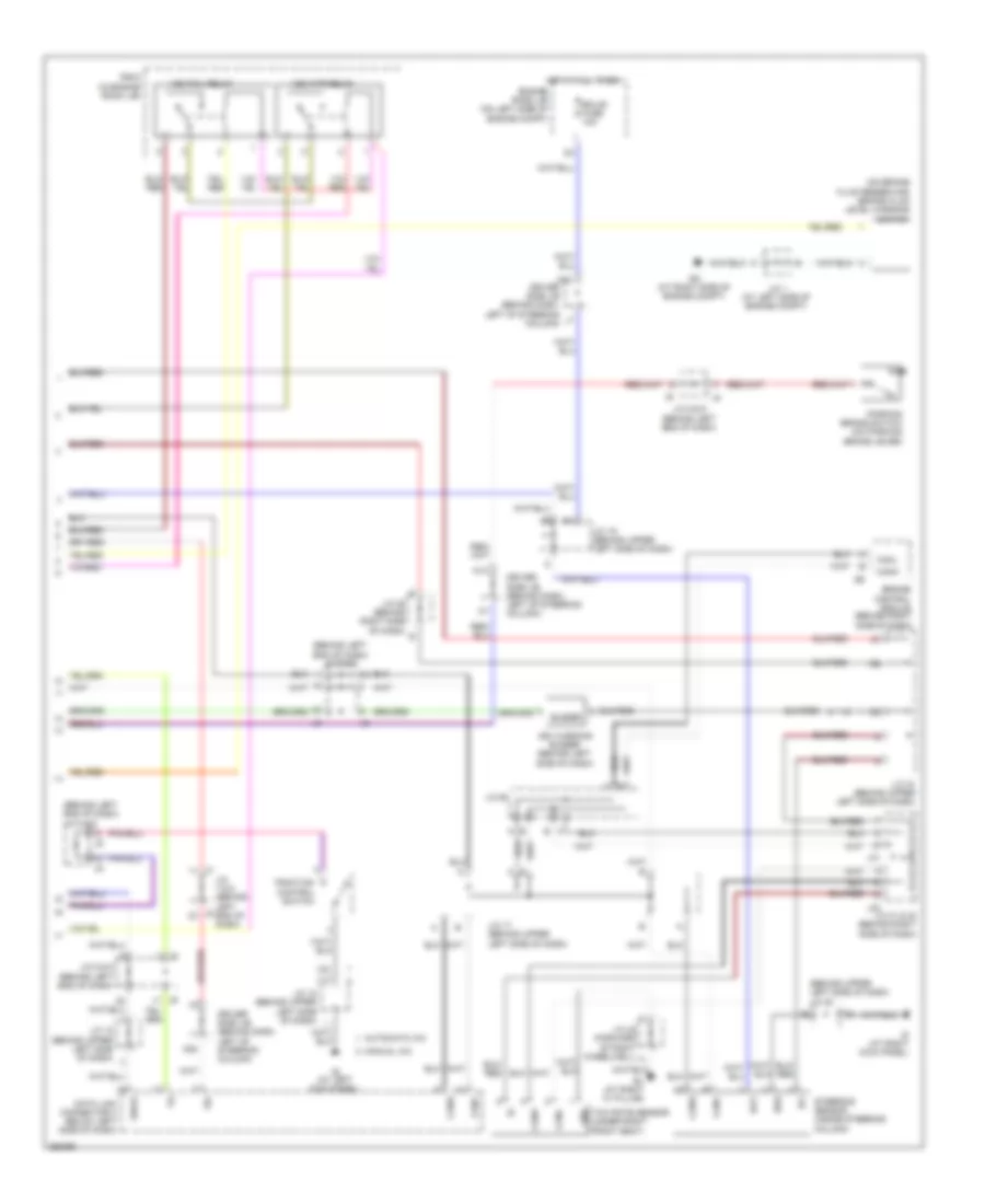
Anti-lock Brakes Wiring Diagram, with VSC (1 of 2) for Toyota Sienna CE 2009

List of elements for Anti-lock Brakes Wiring Diagram, with VSC (1 of 2) for Toyota Sienna CE 2009:
- (at left side of engine compt) ed
- (in engine room j/b)
- (w/ dynamic laser cruise) control) r/b 6
- +bs
- Abs 1 fuse 50a
- Abs 2 fuse 30a
- Abs ind
- Brake ind
- Brk relay
- Brl
- C16
- C21
- Canh
- Canl
- Combination meter
- Csw
- D/g
- Driver side j/b (behind dash, left of steering column)
- Driver side j/b (behind dash, left of steering column) j6 j/c 5 & 6 (behind left end of dash) j5
- Ecu-ig fuse 10a
- F10
- F12
- Fl+
- Fl-
- Fr+
- Fr-
- Fusible link block (on left side of engine compt, inside engine room j/b)
- Gauge 2 fuse 7.5a
- Gnd1
- Gnd2
- H25
- Hot at all times
- Hot in on or start
- If (behind lower center of dash)
- Ig1
- Ind
- J/c 15 (behind left end of dash)
- J/c 2 (at left side of engine compt) a
- J/c 7 & 8 (behind left end of dash)
- K15
- L23
- Left front abs speed sensor (mounted on hub assembly of left front wheel)
- Left rear abs speed sensor (mounted on hub assembly of left rear wheel)
- Mrf
- Pkb
- Red
- Right front abs speed sensor (mounted on hub assembly of right front wheel)
- Right rear abs speed sensor (mounted on hub assembly of right rear wheel)
- Rl+
- Rl-
- Rr+
- Rr-
- Skid control ecu w/ actuator (at left rear of engine compartment)
- Slip ind
- Speedometer
- Stop fuse 10a
- Stop light switch (w/ dynamic laser cruise control) (on bracket, above brake pedal)
- Stp1
- Stp2
- Stpo
- Tire pressure
- Trac off ind
- Vsc ind
- W/ dynamic laser cruise control
- W/o dynamic laser cruise control
- Wfse
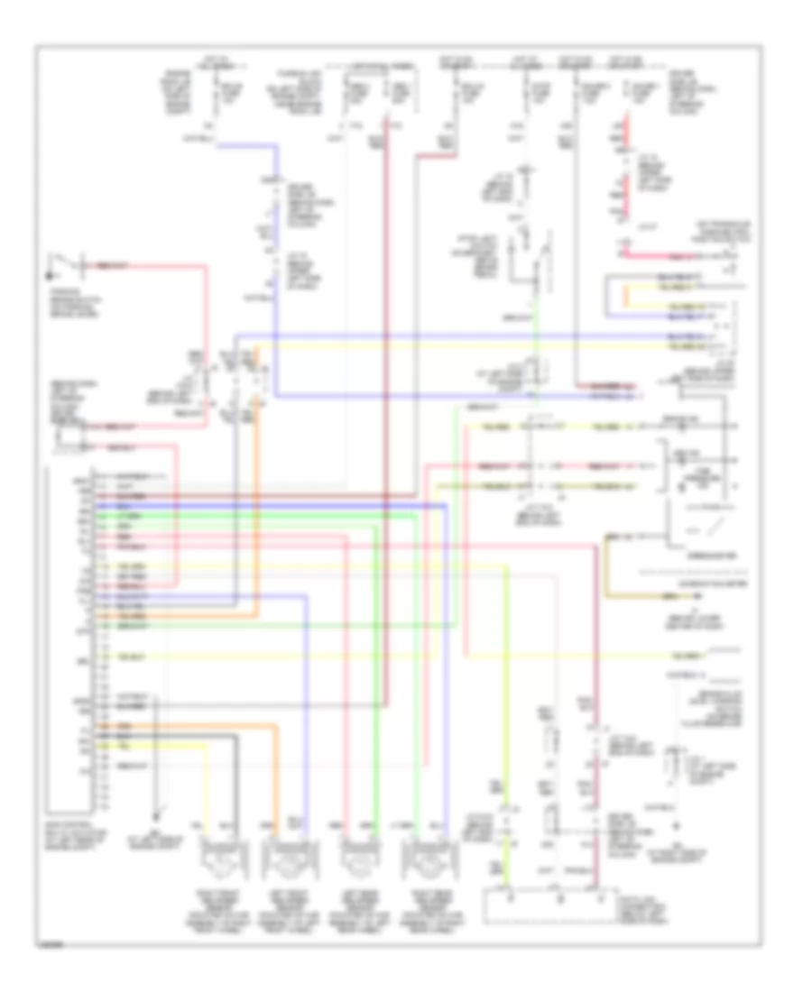
Anti-lock Brakes Wiring Diagram, with VSC (2 of 2) for Toyota Sienna CE 2009
List of elements for Anti-lock Brakes Wiring Diagram, with VSC (2 of 2) for Toyota Sienna CE 2009:
- (behind left end of dash) j/c 5 & 6
- (behind upper left side of dash) j/c 20
- (on brake fluid reservoir) brake fluid level warning switch
- Automatic a/c
- Bat
- Bl (at right "c" pillar)
- Buzzer
- C24
- Canh
- Canl
- Data link connector 3 below left side of dash)
- Driver side j/b (behind dash, left of steering column)
- Ea (at right side of engine compt)
- Ecu-b fuse 10a
- Engine control module (behind right side of dash)
- Engine room j/b (on left side of engine compt)
- Ess
- Gnd
- Hot at all times
- Ie (at left kick panel)
- Ig (at right kick panel)
- Ig1
- J/c 1 (at left side of engine compt)
- J/c 17 (behind upper left side of dash)
- J/c 18 (behind upper left side of dash)
- J/c 19 (behind upper left side of dash)
- J/c 28 (behind right side of dash)
- J/c 31 & 32 (behind right side of dash)
- J/c 42 (forward of right wheelwell) a
- J/c 49
- J/c 5 & 6 (behind left end of dash)
- J31
- J32
- J7 j/c 7 & 8 (behind left j8 end of dash)
- K10
- K28
- Manual a/c
- Parking brake switch (on parking brake lever)
- R/b 5 (in engine room j/b)
- Sil
- Steering sensor (inside steering column)
- Traction control switch
- Vsc fail relay
- Vsc mtr relay
- Vsc warning buzzer (behind left side of dash)
- Wsfe
- Yaw rate sensor (under right front seat)
Anti-lock Brakes Wiring Diagram, without VSC for Toyota Sienna CE 2009
List of elements for Anti-lock Brakes Wiring Diagram, without VSC for Toyota Sienna CE 2009:
- (behind dash, left of steering column) driver side j/b
- (on transaxle) park/neutral position switch
- +bm
- +bs
- Abs 1 fuse 50a
- Abs 2 fuse 30a
- Abs ind
- Brake fluid level warning switch (on brake fluid reservoir)
- Brake ind
- Brl
- C16
- C24
- Combination meter
- D/g
- Data link connector 3 (below left side of dash)
- Driver side j/b (behind dash, left of steering column)
- Ea (at right side of engine compt)
- Ecu-b fuse 10a
- Ecu-ig fuse 10a
- Ed (at left side of engine compt)
- Engine room j/b (on left side of engine compt)
- F10
- F12
- Fl+
- Fl-
- Fr+
- Fr-
- Fusible link block (on left side of engine compt, inside engine room j/b)
- Gauge 1 fuse 10a
- Gauge 2 fuse 7.5a
- Gnd1
- Gnd2
- H25
- Hot at all times
- Hot in on or start
- If (behind lower center of dash)
- Ig1
- J/c 1 (at left side of engine compt)
- J/c 15 (behind left end of dash)
- J/c 18 (behind upper left side of dash)
- J/c 19 (behind upper left side of dash)
- J/c 2 (at left side of engine compt)
- J/c 20 (behind upper left side of dash)
- J/c 47
- J/c 5 & 6 (behind left end of dash)
- J/c 7 & 8 (behind left end of dash)
- K10
- K14
- K28
- L10
- L26
- Left front abs speed sensor (mounted on hub assembly of left front wheel)
- Left rear abs speed sensor (mounted on hub assembly of left rear wheel)
- Parking brake switch (on parking brake lever)
- Pkb
- Pnk
- Red
- Right front abs speed sensor (mounted on hub assembly of right front wheel)
- Right rear abs speed sensor (mounted on hub assembly of right rear wheel)
- Rl+
- Rl-
- Rr+
- Rr-
- Sil
- Skid control ecu w/ actuator (at left rear of engine compt)
- Speedometer
- Stop fuse 10a
- Stop light switch (on bracket, above brake pedal)
- Stp
- Tire pressure ind