ANTI-LOCK BRAKES
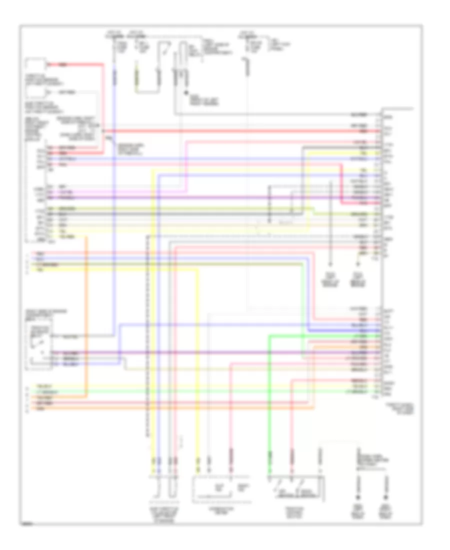
Anti-lock Brake Wiring Diagrams, with Traction Control (1 of 2) for Toyota Supra 1998

List of elements for Anti-lock Brake Wiring Diagrams, with Traction Control (1 of 2) for Toyota Supra 1998:
- (dash harn, left end of dash)
- (dash harn, left end of dash) i2
- (engine harn, right front of engine compt) e6
- A20
- A21
- Abs
- Abs actuator (right rear of engine compartment)
- Abs deceleration sensor (below front console, forward of gear selector)
- Abs ecu (below center of dash)
- Abs fuse 1 60a
- Abs ind
- Abs motor relay
- Abs solenoid relay
- Ast
- D/g
- Data link connector 1 (right side of firewall)
- Data link connector 2 (below dash, left of steering column)
- Ecu-ig fuse 10a
- Exo
- Fl+
- Fl-
- Flo
- Fr+
- Fr-
- Fro
- G101 (front of right front fender)
- G201 (right end of dash)
- G202 (left end of dash)
- Gauge fuse 10a
- Ggnd
- Gl1
- Gl2
- Gnd1
- Gnd2
- Hot at all times
- Hot in run or start
- I14
- I18
- Ig1
- J/b 1 (left kick panel)
- Left front abs speed sensor
- Left rear abs speed sensor
- Left telltale light
- Opa
- Pnk
- R/b 2 (left side of engine compartment)
- R/b 5 (right side of engine compartment)
- Red
- Right front abs speed sensor
- Right rear abs speed sensor
- Rl+
- Rl-
- Rlo
- Rr+
- Rr-
- Rro
- Sflh
- Sflr
- Sfrh
- Sfrr
- Shield
- Srlh
- Srlr
- Srrh
- Srrr
- Stop fuse 15a
- Stop light switch
- Stp
- Trac off ind
- Vgs
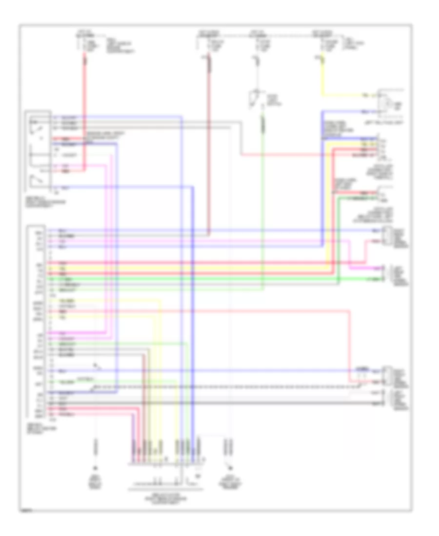
Anti-lock Brake Wiring Diagrams, with Traction Control (2 of 2) for Toyota Supra 1998
List of elements for Anti-lock Brake Wiring Diagrams, with Traction Control (2 of 2) for Toyota Supra 1998:
- (below right front footrest) engine control module
- (engine harn, right side of firewall)
- (engine harn, right side of firewall) e16 i17 (dash harn, right side of dash)
- (m/t) (a/t)
- (right side of engine compartment) r/b 5
- Abs
- Batt
- Combination meter
- Csw
- E10
- E16
- Ecu-b fuse 10a
- Efi 1 fuse 30a
- Efi main relay
- Efi+
- Efi-
- Efib
- Efif
- Eo1
- Etc+
- Etc-
- Fail
- Flo
- Fro
- G100 (front of left front fender)
- G110 (left front of engine)
- G114 (left rear of engine)
- G201 (right end of dash)
- G202 (left end of dash)
- Ge11
- Ge12
- Geo1
- Hot at all times
- Idl1
- Idl2
- Ind
- J/b 1 (left kick panel)
- M-rel
- Neo
- Off switch
- Pnk
- R/b 2 (left side of engine compartment)
- Red
- Rlo
- Rly+
- Rly-
- Rro
- Shield
- Sind
- Slip ind
- Snow
- Snow ind
- Snow switch
- Sub throttle position sensor (on throttle body)
- Sub throttle valve motor (left front of engine)
- T15
- T16
- Throttle ecu (right side of dash)
- Throttle position sensor (on throttle body)
- Trac fuse 7.5a
- Traction control switch
- Traction solenoid relay
- Vta1
- Vto1
- Vto2
Anti-lock Brake Wiring Diagrams, without Traction Control for Toyota Supra 1998
List of elements for Anti-lock Brake Wiring Diagrams, without Traction Control for Toyota Supra 1998:
- (dash harn, left end of dash) i2
- (dash harn, lower left side of center console) i9
- (engine harn, front of engine compt) e18
- A18
- A19
- Abs
- Abs actuator (right rear of engine compartment)
- Abs ecu (below center of dash)
- Abs fuse 1 60a
- Abs ind
- Abs relay (right side of engine compartment)
- Ast
- D/g
- Data link connector 1 (right side of firewall)
- Data link connector 2 (below dash, left of steering column)
- Ecu-ig fuse 10a
- Fl+
- Fl-
- Fr+
- Fr-
- G101 (front of right front fender)
- G201 (right end of dash)
- Gauge fuse 10a
- Gnd1
- Gnd2
- Hot at all times
- Hot in run or start
- Ig1
- J/b 1 (left kick panel)
- Left front abs speed sensor
- Left rear abs speed sensor
- Left telltale light
- Pnk
- R/b 2 (left side of engine compartment)
- Red
- Right front abs speed sensor
- Right rear abs speed sensor
- Rl+
- Rl-
- Rr+
- Rr-
- Sflh
- Sflr
- Sfrh
- Sfrr
- Shield
- Srh
- Srr
- Stop fuse 15a
- Stop light switch
- Stp