ANTI-LOCK BRAKES
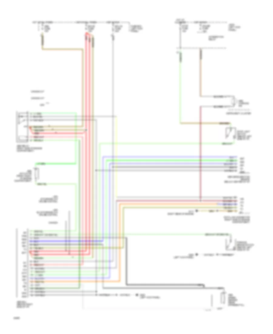
Rear ABS Wiring Diagram for Toyota T100 SR5 1994
List of elements for Rear ABS Wiring Diagram for Toyota T100 SR5 1994:
- Abs actuator (front right of engine compartment)
- Abs deceleration sensor (below center of i/p)
- Abs ecu (behind right side of i/p)
- Abs fuse 15a
- Abs relay (right side of engine compartment)
- Abs speed sensor (rear differential)
- Abs warning ind
- Bat
- Canada
- Canada a/t
- Canada m/t
- Data link connector (right side of engine compartment)
- Ecu-b fuse 15a
- Ecu-ig fuse 20a
- Fuse box (left kick panel)
- G117 (right rear of engine)
- G200 (left kick panel)
- Gauge fuse 10a
- Gnd
- Gs1
- Gs2
- Gst
- Hot at all times
- Hot in run
- Ig1
- Instrument cluster
- Integration relay
- J/b #1 (left kick panel)
- Nca
- Parking brake switch (behind left side of i/p)
- Pkb
- Red
- Rr+
- Rr-
- Rss
- Stop fuse 15a
- Stop light switch (behind left side of i/p)
- Stp
- Usa
- Usa ex std grade w/o cruise control
- Usa std grade w/o cruise control
 Русский