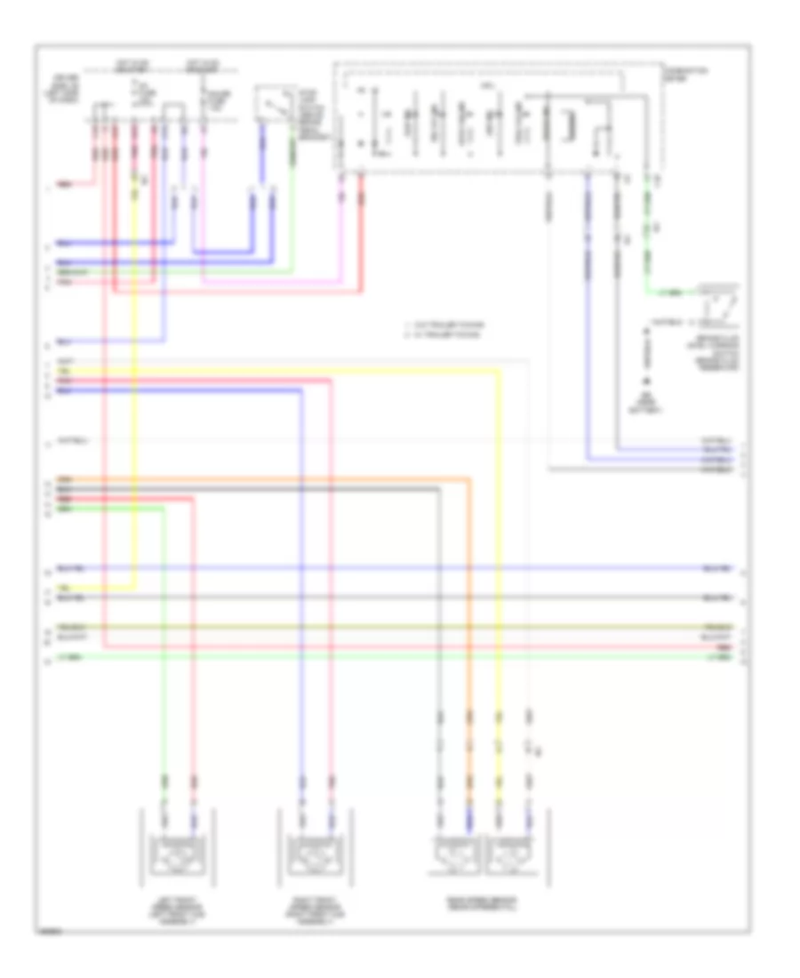
ANTI-LOCK BRAKES
Anti-lock Brakes Wiring Diagram, Hydraulic Booster Type (1 of 3) for Toyota Tacoma 2012

List of elements for Anti-lock Brakes Wiring Diagram, Hydraulic Booster Type (1 of 3) for Toyota Tacoma 2012:
- (right side of dash) (a/t) instrument panel j/b 2
- +bm1
- +bm2
- +bs
- A-trac switch
- A33
- A39
- Abs 1 fuse 50a
- Abs 2 fuse 30a
- Atrc
- Brake fluid level warning switch (brake fluid reservoir)
- C17
- C18
- Canh
- Canl
- Csw
- Downhill assist control switch (if equipped)
- Driver side j/b (left side of dash)
- Ea (right front fender)
- Eb (near battery)
- Ecu-b fuse 7.5a
- Engine room j/b (left side of engine compt)
- Engine room r/b (left front of engine compt)
- Exi
- Exi3
- Exi4
- Fl+
- Fl-
- Fr+
- Fr-
- Gnd1
- Gnd2
- Gnd3
- H13
- Hdcs
- Hot at all times
- Hot in on or start
- Ia1
- Ia3
- Ig1
- Ig1 fuse 10a
- Ig2
- Ign fuse 15a
- Interior lights system
- J/c 13 (behind right kick panel)
- J/c 14 (behind right kick panel)
- Lbl
- Park/ neutral position switch (a/t) (transmission)
- Pkb
- Pnk
- Red
- Rl+
- Rl-
- Rr+
- Rr-
- Skid control ecu w/ actuator (left rear of engine compt)
- Stp
- Stp2
- Stpo
- T17
- T18
- Traction control switch
- Transmissions system
- Vsc off switch
Anti-lock Brakes Wiring Diagram, Hydraulic Booster Type (2 of 3) for Toyota Tacoma 2012
List of elements for Anti-lock Brakes Wiring Diagram, Hydraulic Booster Type (2 of 3) for Toyota Tacoma 2012:
- A-trac ind
- A/t
- Abs ind
- Auto lsd ind
- Bat
- Brake ind
- Buzzer
- C15
- C16
- Canh
- Canl
- Combination meter
- Cpu
- Dac ind
- Data link connector 3 (below left center of dash)
- Driver side j/b (left side of dash)
- Ess
- Gauge fuse 7.5a
- Hot in run or start
- Ia1
- Ib1
- Ic (center of dash)
- Instrument panel j/b 1 (left side of dash)
- J/c 5 (behind right side of dash)
- K13
- Left front speed sensor (left front hub assembly)
- M/t
- Parking brake switch (base of park brake lever)
- Pnk
- Rear speed sensor (rear differential)
- Red
- Right front speed sensor (right front hub assembly)
- Slip ind
- Steering sensor (steering wheel)
- Vsc off ind
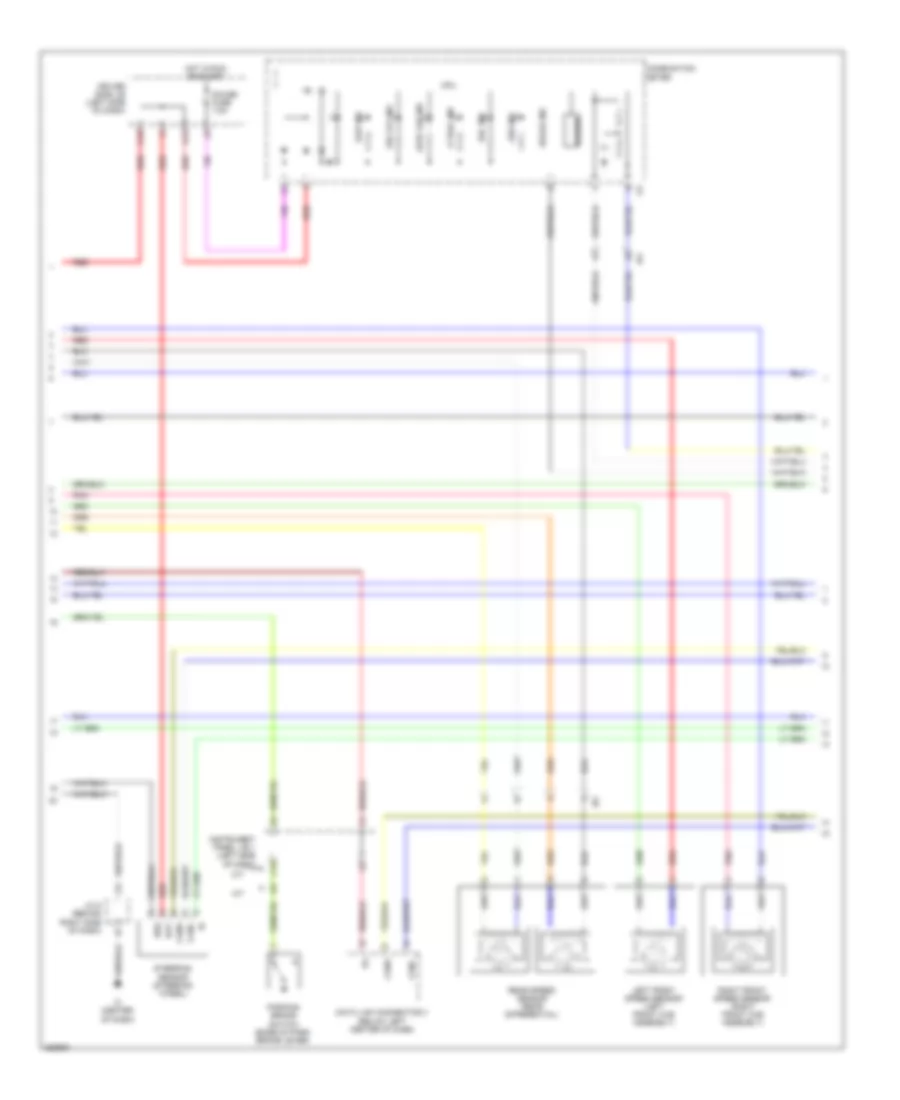
Anti-lock Brakes Wiring Diagram, Hydraulic Booster Type (3 of 3) for Toyota Tacoma 2012
List of elements for Anti-lock Brakes Wiring Diagram, Hydraulic Booster Type (3 of 3) for Toyota Tacoma 2012:
- A12
- Ba (under driver's seat)
- C13
- C14
- C15
- Canh
- Canl
- D12
- D13
- Driver side j/b (left side of dash)
- E14
- Engine control module (behind right side of dash)
- Engine room r/b (left front of engine compt)
- F10
- Gnd
- H18
- Hot at all times
- Hot in on or start
- Ia3
- Ie2
- Ig1 2 fuse 10a
- Ig1 fuse 10a
- Instrument panel j/b 1 (left side of dash)
- Instrument panel j/b 2 (right side of dash)
- J/c 1 (left kick panel)
- J/c 18 (rear of engine)
- J/c 19 (left side of dash)
- Pnk
- Stop fuse 10a
- Stop lamp switch (above brake pedal bracket)
- Stop lp ctrl relay
- Transmissions system
- Yaw rate sensor (under passenger seat)
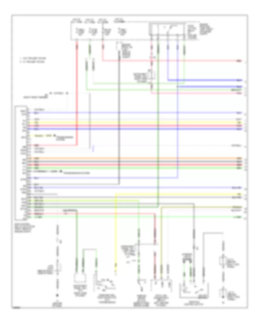
Anti-lock Brakes Wiring Diagram, Vacuum Booster Type (1 of 3) for Toyota Tacoma 2012
List of elements for Anti-lock Brakes Wiring Diagram, Vacuum Booster Type (1 of 3) for Toyota Tacoma 2012:
- (4wd)
- +bs
- A/t
- Abs 1 fuse 50a
- Abs 2 fuse 30a
- C15
- C18
- Canh
- Canl
- Csw
- Data link connector 3 (below left center of dash)
- Dl nl
- Ea (right front fender)
- Ecu-b fuse 7.5a
- Engine room j/b (left side of engine compt)
- Engine room r/b (left front of engine compt)
- Exi
- Exi3
- Exi4
- F7 pnk
- Fl+
- Fl-
- Fr+
- Fr-
- Gnd1
- Gnd2
- Hot at all times
- Ia1
- Ia3
- Ic (center of dash)
- Ig1
- Instrument panel j/b 1 (left side of dash)
- Instrument panel j/b 2 (a/t) (right side of dash)
- Instrument panel j/b 2 (right side of dash)
- Interior lights system
- J/c 13 (behind right kick panel)
- J/c 14 (behind right kick panel)
- J/c 5 (4wd) (behind right side of dash)
- M/t
- Neo
- Park/neutral position switch (a/t) (transmission)
- Parking brake switch (base of park brake lever)
- Pkb
- Pnk
- Red
- Rl+
- Rl-
- Rr+
- Rr-
- Skid control ecu w/ actuator (right rear of engine compt)
- Stop fuse 10a
- Stop lp ctrl relay (w/ trailer towing)
- Stp
- Stp2
- Stpo
- Traction control switch
- Transmissions system
- Vsc off switch
- W/ trailer towing
- W/o trailer towing
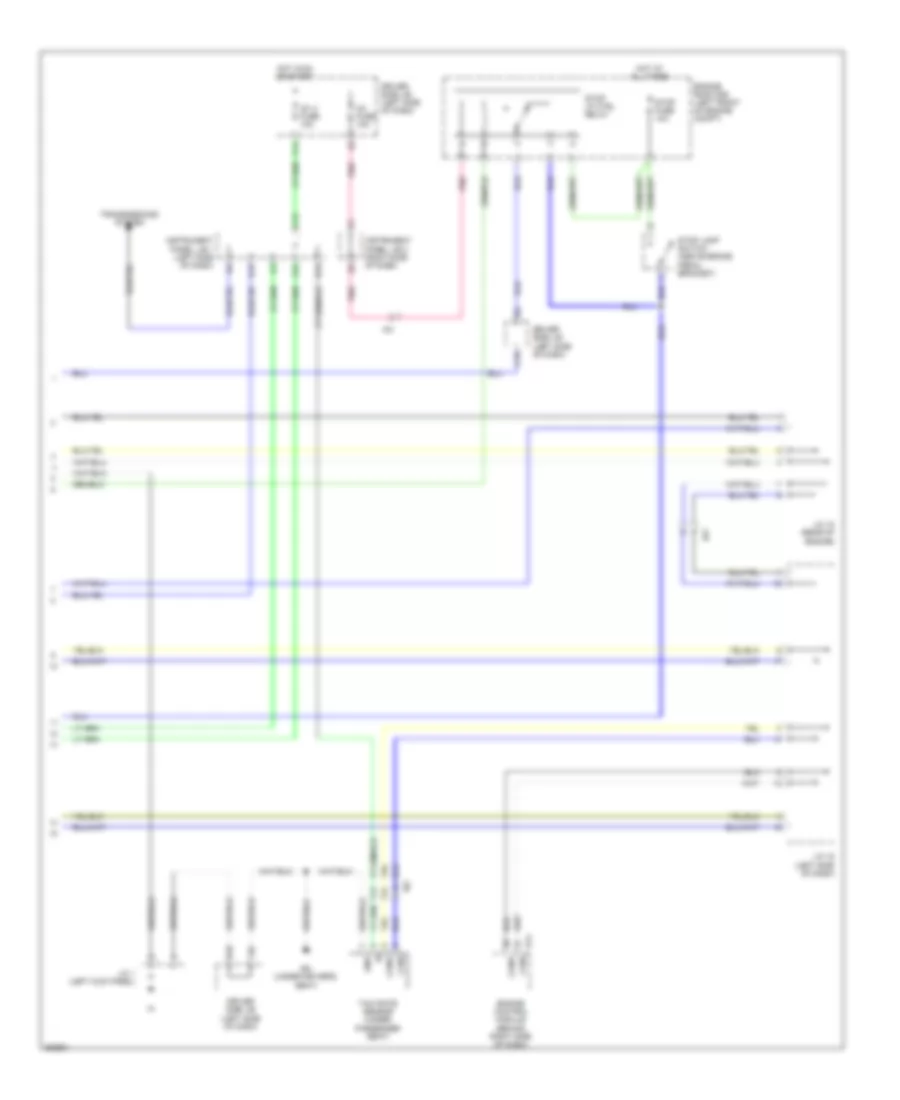
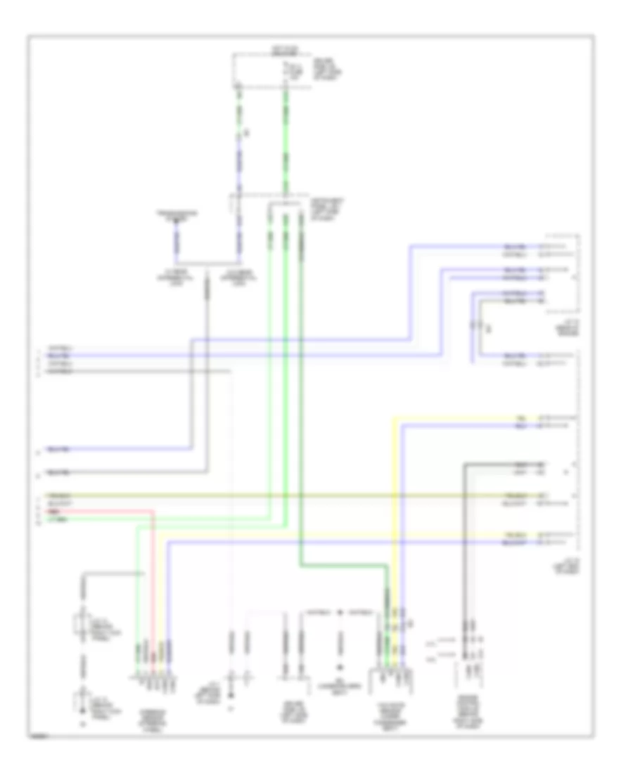
Anti-lock Brakes Wiring Diagram, Vacuum Booster Type (2 of 3) for Toyota Tacoma 2012
List of elements for Anti-lock Brakes Wiring Diagram, Vacuum Booster Type (2 of 3) for Toyota Tacoma 2012:
- Abs ind
- Auto lsd ind
- Brake fluid level warning switch (brake fluid reservoir)
- Brake ind
- Buzzer
- C10
- C15
- C16
- Combination meter
- Cpu
- Driver side j/b (left side of dash)
- Eb (near battery)
- Gauge fuse 7.5a
- H13
- Hot in on or start
- Ia1
- Ib1
- Ig1 fuse 10a
- Ih1
- K13
- Left front speed sensor (left front hub assembly)
- Pnk
- Rear speed sensor (rear differential)
- Red
- Right front speed sensor (right front hub assembly)
- Slip ind
- Stop lamp switch (above brake pedal bracket)
- Trac off ind
- Vsc off ind
- W/ trailer towing
- W/o trailer towing
Anti-lock Brakes Wiring Diagram, Vacuum Booster Type (3 of 3) for Toyota Tacoma 2012
List of elements for Anti-lock Brakes Wiring Diagram, Vacuum Booster Type (3 of 3) for Toyota Tacoma 2012:
- 2.7l
- 4.0l
- A12
- A13
- Ba (under driver's seat)
- Bat
- C13
- C14
- Canh
- Canl
- D12
- Driver side j/b (left side of dash)
- E14
- Engine control module (behind right side of dash)
- Ess
- F10
- Gnd
- H18
- Hot in on or start
- Ia3
- Ib1
- Ie2
- Ig1 2 fuse 10a
- Instrument panel j/b 1 (left side of dash)
- J/c 1 (behind left side of dash)
- J/c 13 (behind right kick panel)
- J/c 14 (behind right kick panel)
- J/c 18 (rear of engine)
- J/c 19 (left end of dash)
- Red
- Steering sensor (steering wheel)
- Transmissions system
- W/ rear differential lock
- W/o rear differential lock
- Yaw rate sensor (under passenger seat)