ANTI-LOCK BRAKES
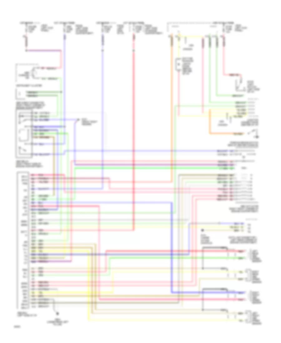
Anti-lock Brake Wiring Diagrams for Toyota Tercel 1994
List of elements for Anti-lock Brake Wiring Diagrams for Toyota Tercel 1994:
- A10
- A11
- A12
- Abs actuator (right front corner of engine compartment)
- Abs check connector (right front corner of engine compartment)
- Abs ecu (left side of i/p)
- Abs fuse 60a
- Abs relay (right front side of engine compartment)
- Abs warning ind
- Ast
- B10
- B11
- B12
- B13
- B14
- B15
- B16
- B17
- B18
- B19
- B20
- B21
- B22
- B23
- B24
- B25
- B26
- Batt
- Canada
- Data link connector 1 (left rear corner of engine compartment)
- Daytime runnung lights diode (behind center of i/p)
- Dome fuse 15a
- Ecu-ig fuse 7.5a
- F/b #2 (left side of i/p)
- Fl+
- Fl-
- Fr+
- Fr-
- Fss
- G101 (front right fender)
- G131 (under intake manifold)
- G904 (under rear left pillar)
- Gauge fuse 10a
- Gnd
- Hot at all times
- Hot in run
- Ig1
- Instrument cluster
- J/b #1 (left kick panel)
- Junction connector #2 (center of i/p)
- Left front abs speed sensor
- Left rear abs speed sensor
- Nca
- Parking brake switch (end of center console)
- Pkb
- Pnk
- R/b #2 (left side of engine compartment)
- Red
- Right front abs speed sensor
- Right rear abs speed sensor
- Rl+
- Rl-
- Rr+
- Rr-
- Rss
- Sflh
- Sflr
- Sfrh
- Sfrr
- Srlh
- Srlr
- Srrh
- Srrr
- Stop fuse 10a
- Stop light switch (left side of i/p)
- Stp
- Usa
 English