ANTI-LOCK BRAKES
Anti-lock Brake Wiring Diagrams for Volkswagen Cabrio GLS 2002
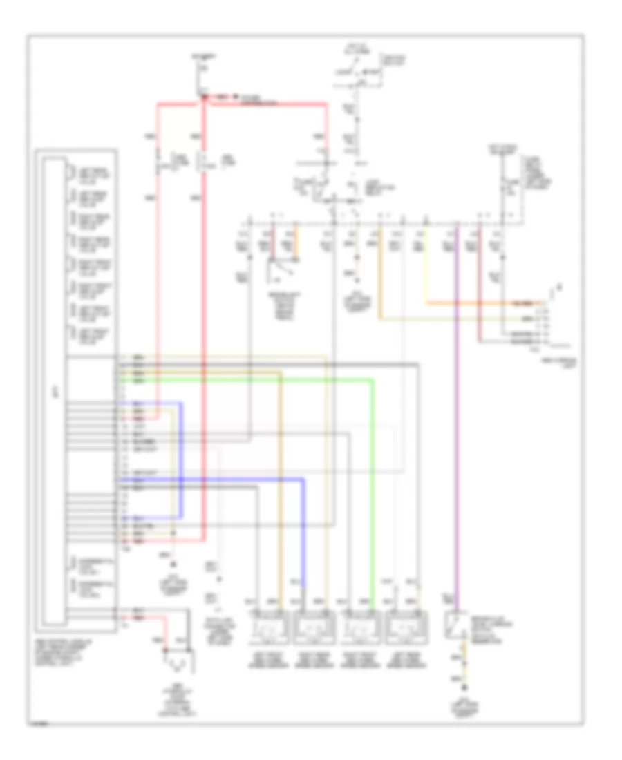
List of elements for Anti-lock Brake Wiring Diagrams for Volkswagen Cabrio GLS 2002:
- 30a
- Abs control module (left rear corner of engine compt, under hydraulic control unit)
- Abs fuse
- Abs hydraulic pump (integral with abs control unit)
- Abs warning light
- Battery
- Brake fluid level warning switch (on fluid reservoir)
- Brakelight switch (above brake pedal)
- C/1
- D/7
- Data link connector (under left side of dash)
- Differential lock valve 1
- Differential lock valve 2
- E/3
- E/4
- Fuse 10a
- Fuse 15a
- Fuse/ relay panel (under left side of dash)
- G12 (left side of engine compt)
- H1/3
- Hot at all times
- Hot in run or start
- Ignition switch
- Left front abs inlet valve
- Left front abs outlet valve
- Left front abs wheel speed sensor
- Left rear abs inlet valve
- Left rear abs outlet valve
- Left rear abs wheel speed sensor
- Load reduction relay
- Lock
- Power distribution
- Red
- Right front abs inlet valve
- Right front abs outlet valve
- Right front abs wheel speed sensor
- Right rear abs inlet valve
- Right rear abs outlet valve
- Right rear abs wheel speed sensor
- Start
- T25
- T7c
- W/2
- W/4
- X/2
- X/3
- X/4
- X/8
- Y/3
 English