ANTI-LOCK BRAKES
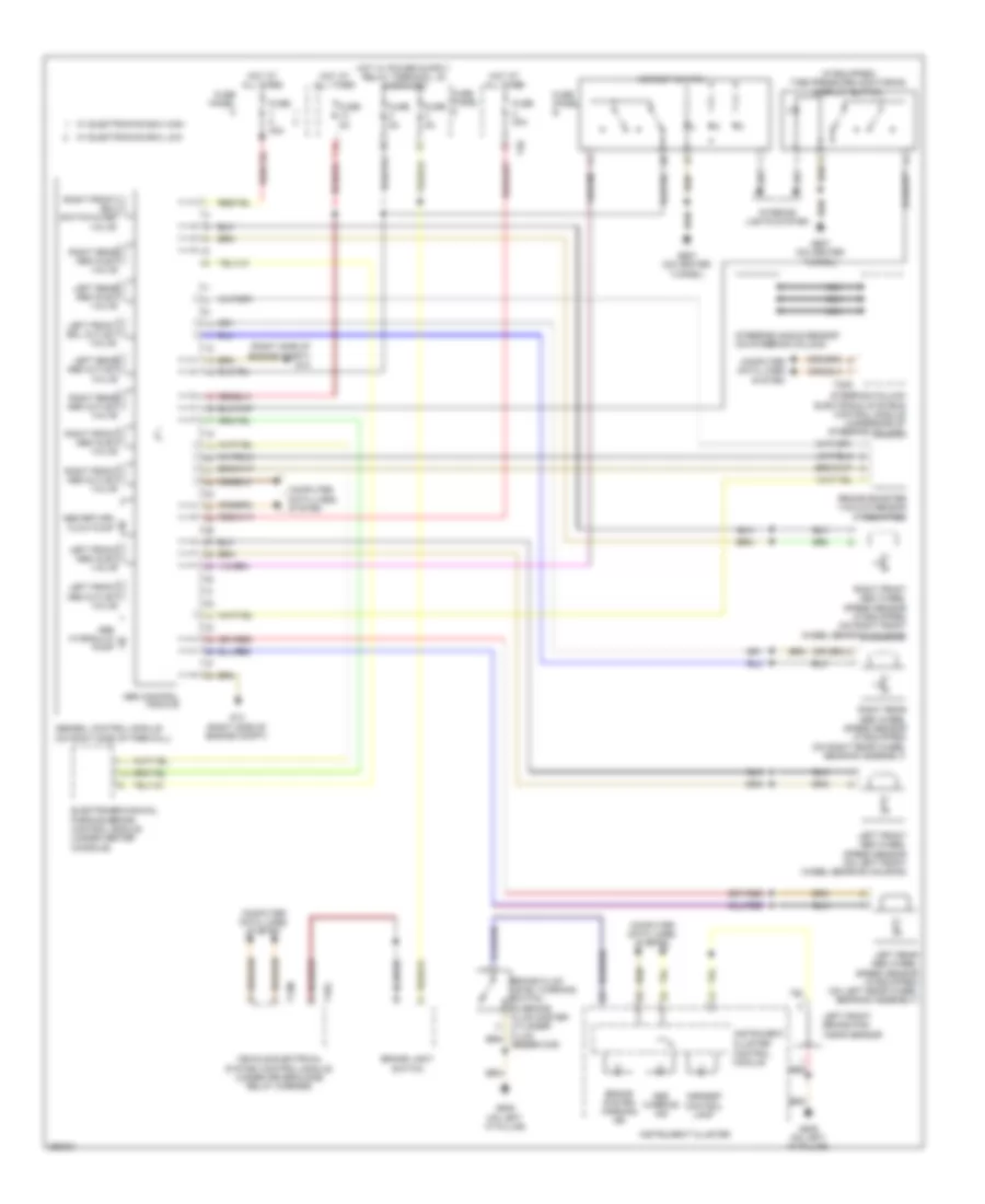
Anti-lock Brakes Wiring Diagram for Volkswagen CC Lux 2011
List of elements for Anti-lock Brakes Wiring Diagram for Volkswagen CC Lux 2011:
- (if equipped) tire pressure monitoring display button
- (right side of engine compt) g13
- 13a
- Abs control module
- Abs hydraulic pump
- Abs return flow pump
- Abs warning ind
- Abs/edl control module (on right side of firewall)
- Asr/esp control lamp
- Asr/esp switch
- Brake booster vacuum sensor (if equipped)
- Brake light switch
- Brake system warning ind
- Cluster
- Computer data lines system
- Control module
- Electromechanical parking brake control module (under center console)
- Fuse 30a
- Fuse 40a
- Fuse 5a
- Fuse panel a
- Fuse panel b
- Fuse panel c
- G13 (right side of engine compt)
- G639 (on left "a" pillar)
- G687 (on center tunnel)
- Hot at all times
- Instrument
- Instrument cluster
- Interior lights system
- Left front abs inlet valve
- Left front abs outlet valve
- Left front abs wheel speed sensor (on left front wheel bearing housing)
- Left front brake pad wear sensor
- Left front edl outlet valve
- Left rear abs inlet valve
- Left rear abs outlet valve
- Left rear abs wheel speed sensor (if equipped) (on left rear wheel bearing assembly)
- Nca
- Red
- Reservoir)
- Right front abs inlet valve
- Right front abs outlet valve
- Right front abs wheel speed sensor (if equipped) (on right front wheel bearing housing)
- Right front edl switch-over valve
- Right rear abs inlet valve
- Right rear abs outlet valve
- Right rear abs wheel speed sensor (if equipped) (on right rear wheel bearing assembly)
- Steering angle sensor (on steering column)
- Steering column electronic systems control module (underside of steering column)
- T12m
- T16g
- T20d
- T40
- Vehicle electrical system control module (under driver's side relay carrier)
- W/ electronics box high
- W/ electronics box low
 English