ANTI-LOCK BRAKES
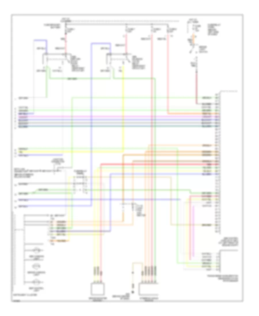
Anti-lock Brake Wiring Diagrams, with Electronic Stability Program (1 of 2) for Volkswagen EuroVan MV 2002

List of elements for Anti-lock Brake Wiring Diagrams, with Electronic Stability Program (1 of 2) for Volkswagen EuroVan MV 2002:
- Abs control module (w/ edl) (at left front of engine compt)
- Abs rtn flow pump
- Abs valves
- Asr/esp switch
- Battery
- Cruise control system
- Fuse 14 10a
- Fuse/relay panel
- Fuse/relay panel (behind left side of dash)
- G1 (battery to body)
- G45 (behind center of dash)
- Hot in on or start
- Interior lights system
- Left front abs wheel speed sensor
- Left rear abs wheel speed sensor
- Lf in
- Lf out
- Lr in
- Lr out
- Parking brake warning light switch
- Red
- Rf in
- Rf out
- Right front abs wheel speed sensor
- Right rear abs wheel speed sensor
- Rr in
- Rr out
- Tc pil
- Traction control hydraulic pump
- Tv 5 junction connector
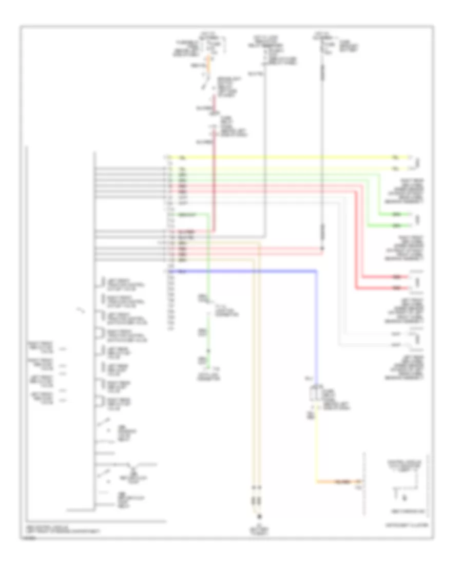
Anti-lock Brake Wiring Diagrams, with Electronic Stability Program (2 of 2) for Volkswagen EuroVan MV 2002
List of elements for Anti-lock Brake Wiring Diagrams, with Electronic Stability Program (2 of 2) for Volkswagen EuroVan MV 2002:
- (behind steering column cover)
- Abs control module (w/ edl) (at left front of engine compt)
- Abs return flow pump relay (near right air outlet)
- Abs solenoid valve relay (near right air outlet)
- Abs warning light
- Brake booster sender 1
- Brake warning light
- Brake- light switch
- Data link connector
- Esp control light
- Fuse 10a
- Fuse 4 50a
- Fuse 6 30a
- Fuse 7 30a
- Fuse 8 5a
- Fuse bracket/ battery
- Fuse/relay panel
- Fuse/relay panel (behind left side of dash)
- G45 (behind center of dash)
- Hot at all times
- Instrument cluster
- Junction connector tv16
- Red
- Steering angle sensor
- T32
- T32a
- Transverse acceleration sensor/rotation rate sensor
- Tv 16 junc- tion con- nector
Anti-lock Brake Wiring Diagrams, without Electronic Stability Program for Volkswagen EuroVan MV 2002
List of elements for Anti-lock Brake Wiring Diagrams, without Electronic Stability Program for Volkswagen EuroVan MV 2002:
- Abs control module (left front of engine compartment)
- Abs return flow pump
- Abs return flow pump relay
- Abs solenoid valve relay
- Abs warning ind
- Brakelight switch (below left side of dash)
- Control module with indicator unit
- Data link connector
- Fuse 10a
- Fuse 5 10a (below fuse/ relay panel)
- Fuse 50a
- Fuse bracket/ battery
- Fuse/ relay panel (behind left side of dash)
- Fuse/relay panel (behind left side of dash)
- G1 (battery to body)
- Hot at all times
- Hot w/ load reduction relay energized
- Instrument cluster
- Left front abs inlet valve
- Left front abs outlet valve
- Left front abs wheel speed sensor (on front of left front wheel bearing assembly)
- Left front traction control outlet valve
- Left front traction control switch-over valve
- Left rear abs inlet valve
- Left rear abs outlet valve
- Left rear abs wheel speed sensor (on back of left rear wheel bearing assembly)
- Red
- Right front abs inlet valve
- Right front abs outlet valve
- Right front abs wheel speed sensor (on front of right front wheel bearing assembly)
- Right front traction control outlet valve
- Right front traction control switch-over valve
- Right rear abs inlet valve
- Right rear abs outlet valve
- Right rear abs wheel speed sensor (on back of right rear wheel bearing assembly)
- T16
- T32
- Tv 14 junction connector