ANTI-LOCK BRAKES
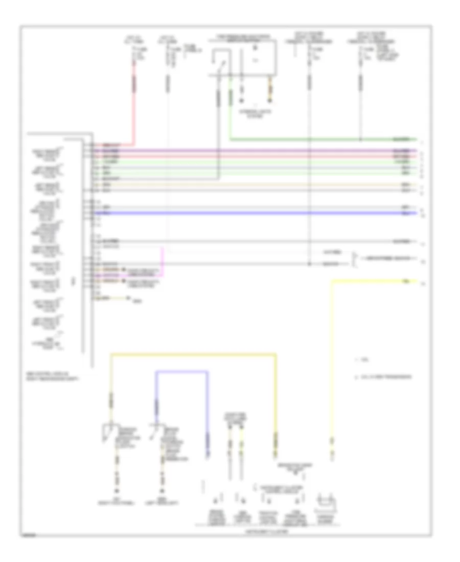
Anti-lock Brakes Wiring Diagram, with ESP (1 of 2) for Volkswagen Golf 2010

List of elements for Anti-lock Brakes Wiring Diagram, with ESP (1 of 2) for Volkswagen Golf 2010:
Anti-lock Brakes Wiring Diagram, with ESP (2 of 2) for Volkswagen Golf 2010
List of elements for Anti-lock Brakes Wiring Diagram, with ESP (2 of 2) for Volkswagen Golf 2010:
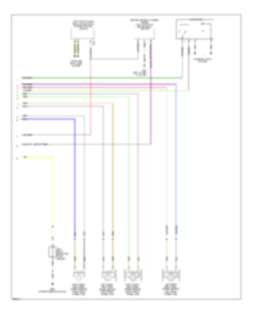
Anti-lock Brakes Wiring Diagram, without ESP (1 of 2) for Volkswagen Golf 2010
List of elements for Anti-lock Brakes Wiring Diagram, without ESP (1 of 2) for Volkswagen Golf 2010:
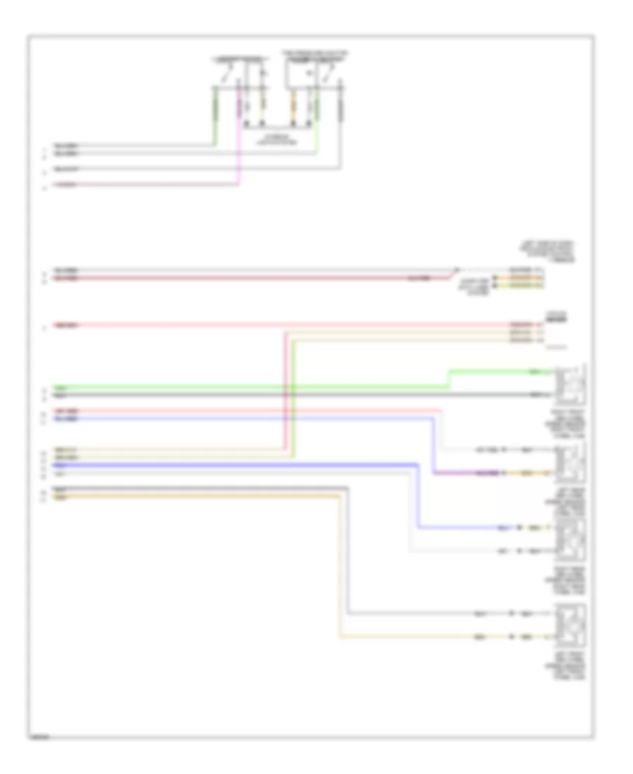
Anti-lock Brakes Wiring Diagram, without ESP (2 of 2) for Volkswagen Golf 2010
List of elements for Anti-lock Brakes Wiring Diagram, without ESP (2 of 2) for Volkswagen Golf 2010: