ANTI-LOCK BRAKES
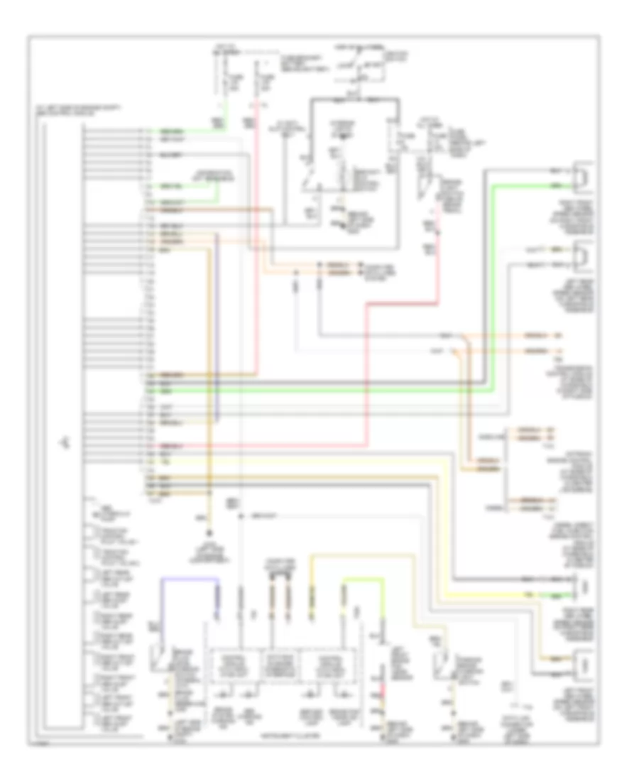
Anti-lock Brake Wiring Diagrams, Early Production for Volkswagen GTI GLX 2001

List of elements for Anti-lock Brake Wiring Diagrams, Early Production for Volkswagen GTI GLX 2001:
Anti-lock Brake Wiring Diagrams, Late Production for Volkswagen GTI GLX 2001
List of elements for Anti-lock Brake Wiring Diagrams, Late Production for Volkswagen GTI GLX 2001: