ANTI-LOCK BRAKES
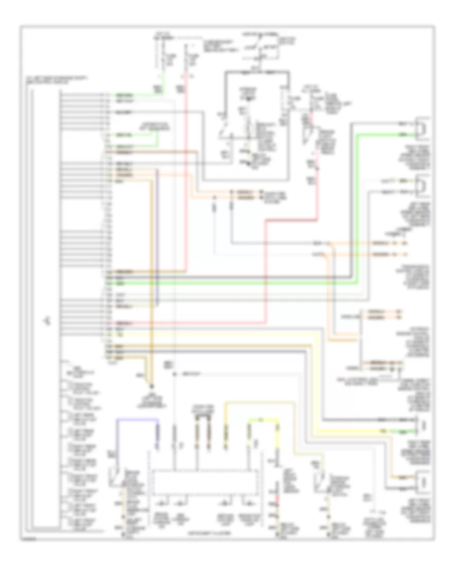
Anti-lock Brakes Wiring Diagram, Early Production with Electronic Stability Program for Volkswagen Jetta GLS 2005

List of elements for Anti-lock Brakes Wiring Diagram, Early Production with Electronic Stability Program for Volkswagen Jetta GLS 2005:
- (at left side of engine compt) abs control module
- (below left side of dash) g42
- (information not avail)
- 13a
- 2004 late prod, 2005 2004 early prod
- 4-motion
- 4-speed
- 5-speed
- Abs hydraulic pump
- Abs warning ind
- Asr/esp control lamp
- Brake booster sender 1
- Brake fluid level warning switch (integral with brake fluid reservoir cap)
- Brake pad wear ind lamp
- Brake system warning ind
- Brake- light switch (above brake pedal)
- Compt) g12
- Computer data lines system
- Data link connector (under left side of dash)
- Diesel
- Diesel direct fuel injection engine control module (at base of windshield in center of plenum)
- Esp/anti- slip control switch
- Fuse 10a
- Fuse 30a
- Fuse 5a
- Fuse bracket/ battery (behind battery)
- Fuse panel (behind left side of 9a dash)
- Fwd
- G42 (below left side of dash)
- G671 (on left front long member)
- Gasoline
- Hot at all times
- Hot in on or start
- Instrument cluster
- Interior lights system
- Left front abs inlet valve
- Left front abs outlet valve
- Left front abs wheel speed sensor (on left front hub/spindle assembly)
- Left front brake pad wear sensor
- Left rear abs inlet valve
- Left rear abs outlet valve
- Left rear abs wheel speed sensor (on left rear hub/spindle assembly)
- Motronic engine control module (at base of windshield in center of plenum)
- Parking brake warning light switch
- Red
- Right front abs inlet valve
- Right front abs outlet valve
- Right front abs wheel speed sensor (on right front hub/spindle assembly)
- Right rear abs inlet valve
- Right rear abs outlet valve
- Right rear abs wheel speed sensor (on right rear hub/spindle assembly)
- Steering angle sensor
- T16
- T32
- T32a
- T47a
- Traction control pilot valve 1
- Traction control pilot valve 2
- Transmission control module (at base of windshield in right side of plenum)
- Transverse acceleration/ rotation rate/ longitudinal acceleration sensor (4-motion)
Anti-lock Brakes Wiring Diagram, Early Production without Electronic Stability Program for Volkswagen Jetta GLS 2005
List of elements for Anti-lock Brakes Wiring Diagram, Early Production without Electronic Stability Program for Volkswagen Jetta GLS 2005:
- (at left side of engine compt) abs control module
- (below left side of dash) g42
- (information not available)
- (on left front of engine compt)
- 13a
- 2004 late prod, 2005 2004 early prod
- 4-speed
- 5-speed
- Abs hydraulic pump
- Abs warning ind
- Brake fluid level warning switch (integral with brake fluid reservoir cap)
- Brake pad wear ind lamp
- Brake system warning ind
- Brake- light switch (above brake pedal)
- Computer data lines system
- Data link connector (under left side of dash)
- Diesel
- Diesel direct fuel injection engine control module (at base of windshield in center of plenum)
- Esp/anti- slip control switch (w/ esp/ anti-slip control)
- Esp/asc control lamp
- Fuse 10a
- Fuse 30a
- Fuse 5a
- Fuse bracket/ battery (behind battery)
- Fuse panel (behind left side of dash)
- G12
- G65 (left side of engine compartment)
- Gasoline
- Hot at all times
- Ignition switch
- Instrument cluster
- Interior lights system
- Left front abs inlet valve
- Left front abs outlet valve
- Left front abs wheel speed sensor (on left front hub/spindle assemble)
- Left front brake pad wear sensor
- Left rear abs inlet valve
- Left rear abs outlet valve
- Left rear abs wheel speed sensor (on left rear hub/spindle assembly)
- Lock
- Motronic engine control module (at base of windshield in center of plenum)
- Parking brake warning light switch
- Red
- Right front abs inlet valve
- Right front abs outlet valve
- Right front abs wheel speed sensor (on right front hub/spindle assembly)
- Right rear abs inlet valve
- Right rear abs outlet valve
- Right rear abs wheel speed sensor (on right rear hub/spindle assemble)
- Start
- T16
- T32
- T32a
- T47a
- Traction control pilot valve 1
- Traction control pilot valve 2
- Transmission control module (at base of windshield in right side of plenum)
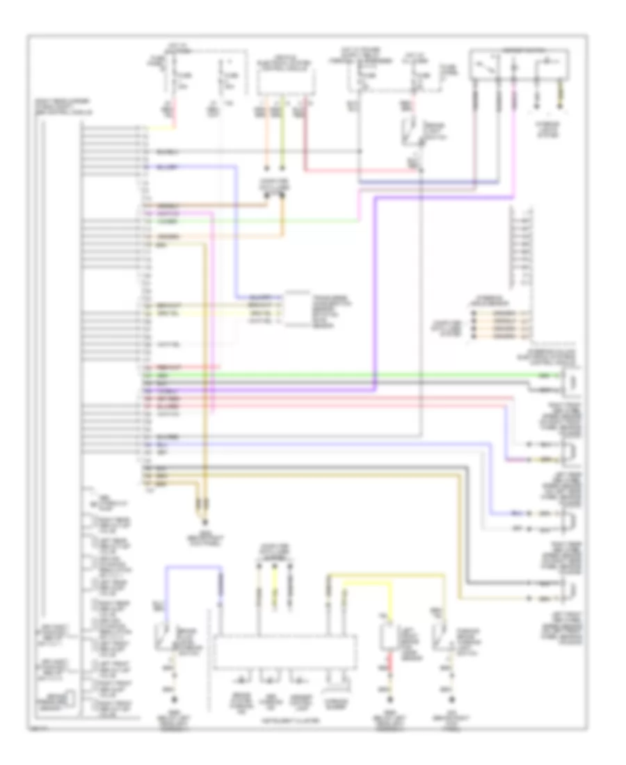
Anti-lock Brakes Wiring Diagram, Late Production with Electronic Stability Program for Volkswagen Jetta GLS 2005
List of elements for Anti-lock Brakes Wiring Diagram, Late Production with Electronic Stability Program for Volkswagen Jetta GLS 2005:
- (right rear corner of eng compt) abs control module
- Abs hydraulic pump
- Abs warning ind
- Asr/esp control lamp
- Asr/esp switch
- Brake fluid level warning switch
- Brake pressure sensor 1
- Brake system warning ind
- Brake- light switch
- Computer data lines system
- Driving dynamics reg hp sw vlv 1
- Driving dynamics reg hp sw vlv 2
- Driving dynamics regulation sw vlv 1
- Fuse 30a
- Fuse 5a
- Fuse panel b
- Fuse panel c
- G43 (behind right kick panel)
- G638 (behind right kick panel)
- G655 (below left headlight assembly)
- Hot at all times
- Instrument cluster
- Interior lights system
- Left front abs inlet valve
- Left front abs outlet valve
- Left front abs wheel speed sensor (on left front wheel bearing housing)
- Left front brake pad wear sensor
- Left rear abs inlet valve
- Left rear abs outlet valve
- Left rear abs wheel speed sensor (on left rear wheel bearing housing)
- Parking brake warning light switch
- Red
- Right front abs inlet valve
- Right front abs outlet valve
- Right front abs wheel speed sensor (on right front wheel bearing housing)
- Right rear abs inlet valve driving dynamics regulation sw vlv 2
- Right rear abs outlet valve
- Right rear abs wheel speed sensor (on right rear wheel bearing housing)
- Steering angle sensor
- Steering column electronic systems control module
- T40
- T47
- Transverse acceleration sensor/ rotation rate sensor
- Vehicle electrical system control module
- Warning buzzer
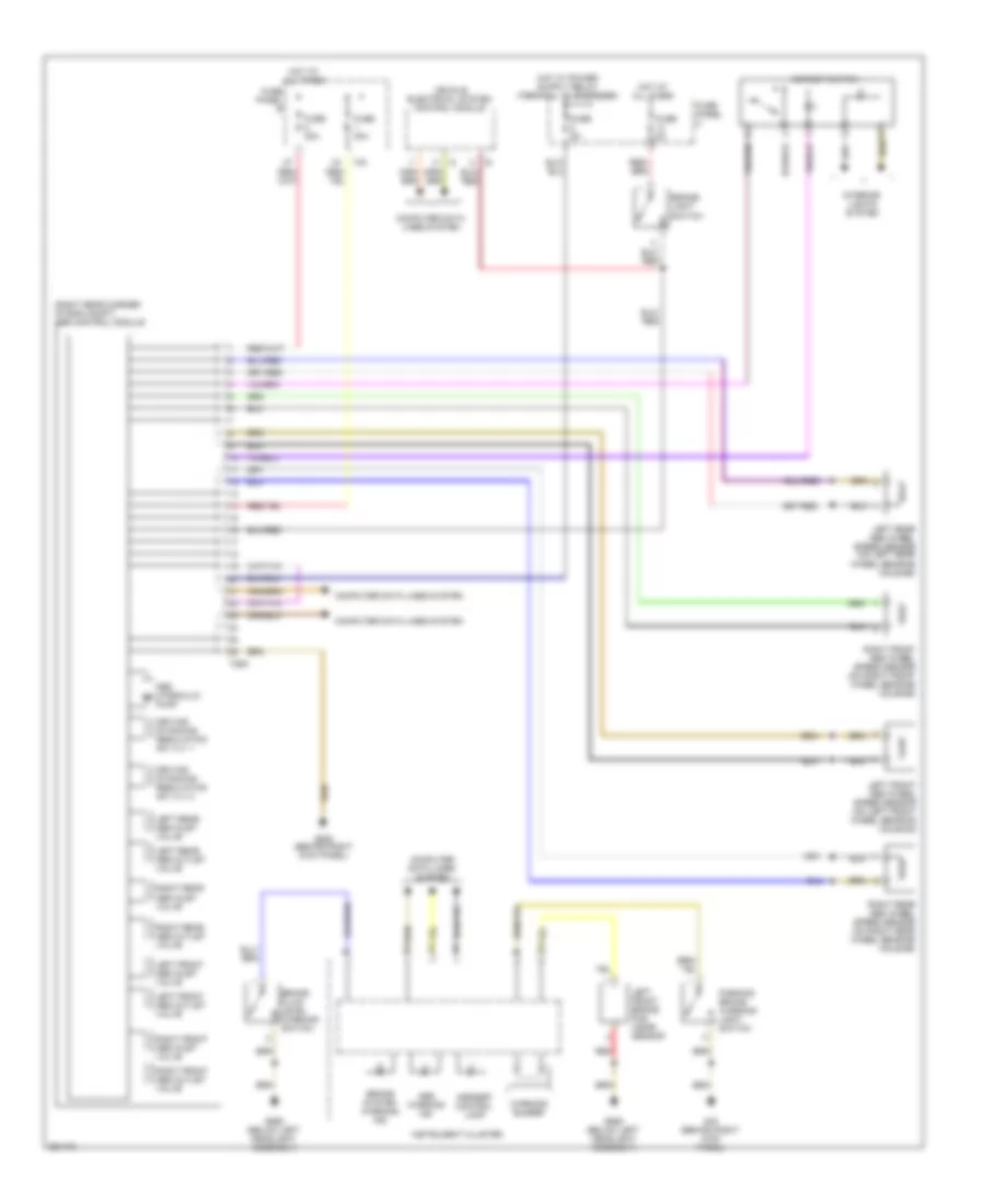
Anti-lock Brakes Wiring Diagram, Late Production without Electronic Stability Program for Volkswagen Jetta GLS 2005
List of elements for Anti-lock Brakes Wiring Diagram, Late Production without Electronic Stability Program for Volkswagen Jetta GLS 2005:
- (right rear corner of eng compt) abs control module
- Abs hydraulic pump
- Abs warning ind
- Asr/esp control lamp
- Asr/esp switch
- Brake fluid level warning switch
- Brake system warning ind
- Brake- light switch
- Computer data lines system
- Driving dynamics regulation sw vlv 1
- Driving dynamics regulation sw vlv 2
- Fuse 30a
- Fuse 5a
- Fuse panel b
- Fuse panel c
- G43 (behind right kick panel)
- G638 (behind right kick panel)
- G655 (below left headlight assembly)
- Hot at all times
- Instrument cluster
- Interior lights system
- Left front abs inlet valve
- Left front abs outlet valve
- Left front abs wheel speed sensor (on left front wheel bearing housing)
- Left front brake pad wear sensor
- Left rear abs inlet valve
- Left rear abs outlet valve
- Left rear abs wheel speed sensor (on left rear wheel bearing housing)
- Parking brake warning light switch
- Red
- Right front abs inlet valve
- Right front abs outlet valve
- Right front abs wheel speed sensor (on right front wheel bearing housing)
- Right rear abs inlet valve
- Right rear abs outlet valve
- Right rear abs wheel speed sensor (on right rear wheel bearing housing)
- T26a
- T40
- Vehicle electrical system control module
- Warning buzzer