ANTI-LOCK BRAKES
Anti-lock Brake Wiring Diagrams, Early Production for Volkswagen New Beetle GLX 2001

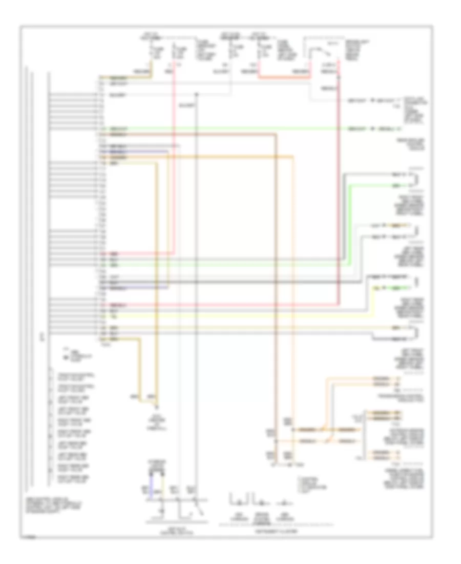
List of elements for Anti-lock Brake Wiring Diagrams, Early Production for Volkswagen New Beetle GLX 2001:
- 1.8l
- 1.9l
- 13a
- 2 (or 4)
- 2.0l
- Abs control module (part of abs hydraulic control unit)
- Abs hydraulic pump (component of abs hydraulic control unit)
- Abs warning
- Asr control lamp
- Asr/esp switch
- Brakelight switch (above brake pedal)
- Control module w/ indicator unit
- Data link connector (dlc) (under left side of dash)
- Diesel direct fuel injection engine control module (below left side of dash panel cover)
- Differential lock valve 1
- Differential lock valve 2
- Fuse 10a
- Fuse 30a
- Fuse 5a
- Fuse bracket
- Fuse panel (behind left side of dash)
- G121 (center of firewall)
- Hot at all times
- Hot in on
- Ignition switch
- Instrument cluster
- Interior lights system
- Left front abs inlet valve
- Left front abs outlet valve
- Left front abs wheel speed sensor (behind left front wheel)
- Left rear abs inlet valve
- Left rear abs outlet valve
- Left rear abs wheel speed sensor (behind left rear wheel)
- Lock
- Motronic engine control module (below left side of dash panel cover)
- Nca
- Rear spoiler control module
- Red
- Right front abs inlet valve
- Right front abs outlet valve
- Right front abs wheel speed sensor (behind right front wheel)
- Right rear abs inlet valve
- Right rear abs outlet valve
- Right rear abs wheel speed sensor (behind right rear wheel)
- Start
- T121
- T16
- T25
- T32a
- T68
- T80
- Transmission control module (tcm) (below right side of dash & defroster duct)
Anti-lock Brake Wiring Diagrams, Late Production for Volkswagen New Beetle GLX 2001
List of elements for Anti-lock Brake Wiring Diagrams, Late Production for Volkswagen New Beetle GLX 2001:
- 1.8l & 2.0l
- 1.9l
- 13a
- 2 (or 4)
- Abs control module (integral w/ abs hydraulic control unit, on left side of engine compt)
- Abs hydraulic pump
- Abs warning
- Anti-slip control switch
- Asc warning
- Brake system warning
- Brakelight switch (above brake pedal
- Control module w/ indicator unit
- Data link connector (dlc) (under left side of dash)
- Diesel direct fuel injection engine control module (below left side of dash panel cover)
- Fuse 10a
- Fuse 30a
- Fuse 5a
- Fuse bracket (on battery cover)
- Fuse panel (behind left side of dash)
- G121 (center of firewall)
- Hot at all times
- Hot in on or start
- Instrument cluster
- Interior lights system
- Left front abs inlet valve
- Left front abs outlet valve
- Left front abs wheel speed sensor (behind left front wheel)
- Left rear abs inlet valve
- Left rear abs outlet valve
- Left rear abs wheel speed sensor (behind left rear wheel)
- Motronic engine control module (below left side of dash panel cover)
- Rear spoiler control module
- Red
- Right front abs inlet valve
- Right front abs outlet valve
- Right front abs wheel speed sensor (behind right front wheel)
- Right rear abs inlet valve
- Right rear abs outlet valve
- Right rear abs wheel speed sensor (behind right rear wheel)
- T121
- T16
- T32a
- T47a
- T68
- Traction control pilot valve 1
- Traction control pilot valve 2
- Transmission control module (tcm)