ANTI-LOCK BRAKES
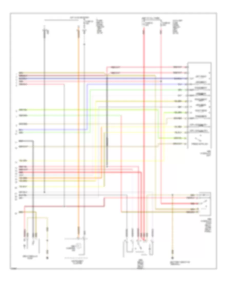
Anti-Lock Brake System Wiring Diagram (1995 Passat Wiring Diagram 1 Of 2) for Volkswagen Passat GLS 1995

List of elements for Anti-Lock Brake System Wiring Diagram (1995 Passat Wiring Diagram 1 Of 2) for Volkswagen Passat GLS 1995:
- (battery to body)
- Abs control module (below left rear seat)
- Abs diagnostic connector (behind fuse/relay panel)
- Acc
- Brake light switch (top of brake pedal support)
- Brake pedal position sensor
- Electronic differential lock cut-off relay
- Electronic differential lock series resistance
- Fuse 20 10a
- Fuse/ relay panel (below left side of i/p)
- G304 (below left rear seat)
- Hot at all times
- Ignition switch
- Left front speed sensor capacitor
- Left front wheel speed sensor
- Left rear wheel speed sensor
- Load reduction relay
- Lock
- Nca
- Red
- Right front speed sensor capacitor
- Right front wheel speed sensor
- Right rear wheel speed sensor
- Start
- To headlight switch
Anti-Lock Brake System Wiring Diagram (1995 Passat Wiring Diagram 2 Of 2) for Volkswagen Passat GLS 1995
List of elements for Anti-Lock Brake System Wiring Diagram (1995 Passat Wiring Diagram 2 Of 2) for Volkswagen Passat GLS 1995:
- Abs hydraulic pump
- Abs hydraulic pump relay (fuse/ relay panel)
- Abs hydraulic unit
- Abs relay (fuse/ relay panel)
- Abs warning ind
- Auxiliary fuse panel (below left side of i/p)
- Diff lock valve 1
- Diff lock valve 2
- Fuse 16 15a
- Fuse 53 30a
- Fuse 54 30a
- Fuse/ relay panel (below left side of i/p)
- Hot at all times
- Hot in on or start
- Instrument cluster
- Left front
- Left rear
- Out
- Press cntrl sw
- Red
- Right front
- Right rear