ANTI-LOCK BRAKES
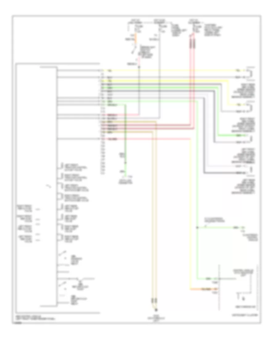
Anti-lock Brake Wiring Diagrams, Early Production, with Traction Control for Volkswagen Passat GLS 2001

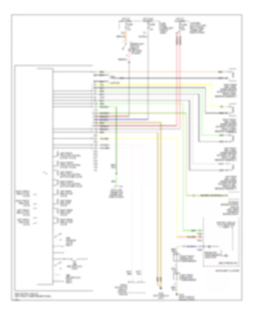
List of elements for Anti-lock Brake Wiring Diagrams, Early Production, with Traction Control for Volkswagen Passat GLS 2001:
- 13a
- Abs control module (left front inner fender panel)
- Abs return flow pump
- Abs return flow pump relay
- Abs solenoid valve relay
- Abs warning ind
- Anti-slip control switch
- Brakelight switch (below left side of dash)
- Climatronic control module
- Control module with indicator unit
- Data link connector
- Fuse 10a
- Fuse 50a
- Fuse panel (under left side of dash)
- G102 (on hydraulic unit)
- G202 (behind left side of dash)
- Hot at all times
- Hot in on & start
- Instrument cluster
- Interior lights system
- Left front abs inlet valve
- Left front abs outlet valve
- Left front abs wheel speed sensor (on front of left front wheel bearing assembly)
- Left front traction control outlet valve
- Left front traction control switch-over valve
- Left rear abs inlet valve
- Left rear abs outlet valve
- Left rear abs wheel speed sensor (on back of left rear wheel bearing assembly)
- Motronic engine control module (left rear corner of engine compt)
- Right front abs inlet valve
- Right front abs outlet valve
- Right front abs wheel speed sensor (on front of right front wheel bearing assembly)
- Right front traction control outlet valve
- Right front traction control switch-over valve
- Right rear abs inlet valve
- Right rear abs outlet valve
- Right rear abs wheel speed sensor (on back of right rear wheel bearing assembly)
- T16
- T18
- T32a
- T32b
- T80
- T88
- Thirteen fold auxiliary relay panel (under left side of dash)
- Traction control ind
- Transmission control module (passenger's side floor cavity)
- W/ climatronic air conditioning
Anti-lock Brake Wiring Diagrams, Early Production, without Traction Control for Volkswagen Passat GLS 2001
List of elements for Anti-lock Brake Wiring Diagrams, Early Production, without Traction Control for Volkswagen Passat GLS 2001:
- 13a
- Abs control module (left front inner fender panel)
- Abs return flow pump
- Abs return flow pump relay
- Abs solenoid valve relay
- Abs warning ind
- Brakelight switch (below left side of dash)
- Climatronic control module
- Control module with indicator unit
- Data link connector
- Fuse 10a
- Fuse 50a
- Fuse panel (under left side of dash)
- G102 (on hydraulic unit)
- Hot at all times
- Hot in on & start
- Instrument cluster
- Left front abs inlet valve
- Left front abs outlet valve
- Left front abs wheel speed sensor (on front of left front wheel bearing assembly)
- Left front traction control outlet valve
- Left front traction control switch-over valve
- Left rear abs inlet valve
- Left rear abs outlet valve
- Left rear abs wheel speed sensor (on back of left rear wheel bearing assembly)
- Right front abs inlet valve
- Right front abs outlet valve
- Right front abs wheel speed sensor (on front of right front wheel bearing assembly)
- Right front traction control outlet valve
- Right front traction control switch-over valve
- Right rear abs inlet valve
- Right rear abs outlet valve
- Right rear abs wheel speed sensor (on back of right rear wheel bearing assembly)
- T16
- T18
- T32a
- T32b
- Thirteen fold auxiliary relay panel (under left side of dash)
- W/ climatronic air conditioning
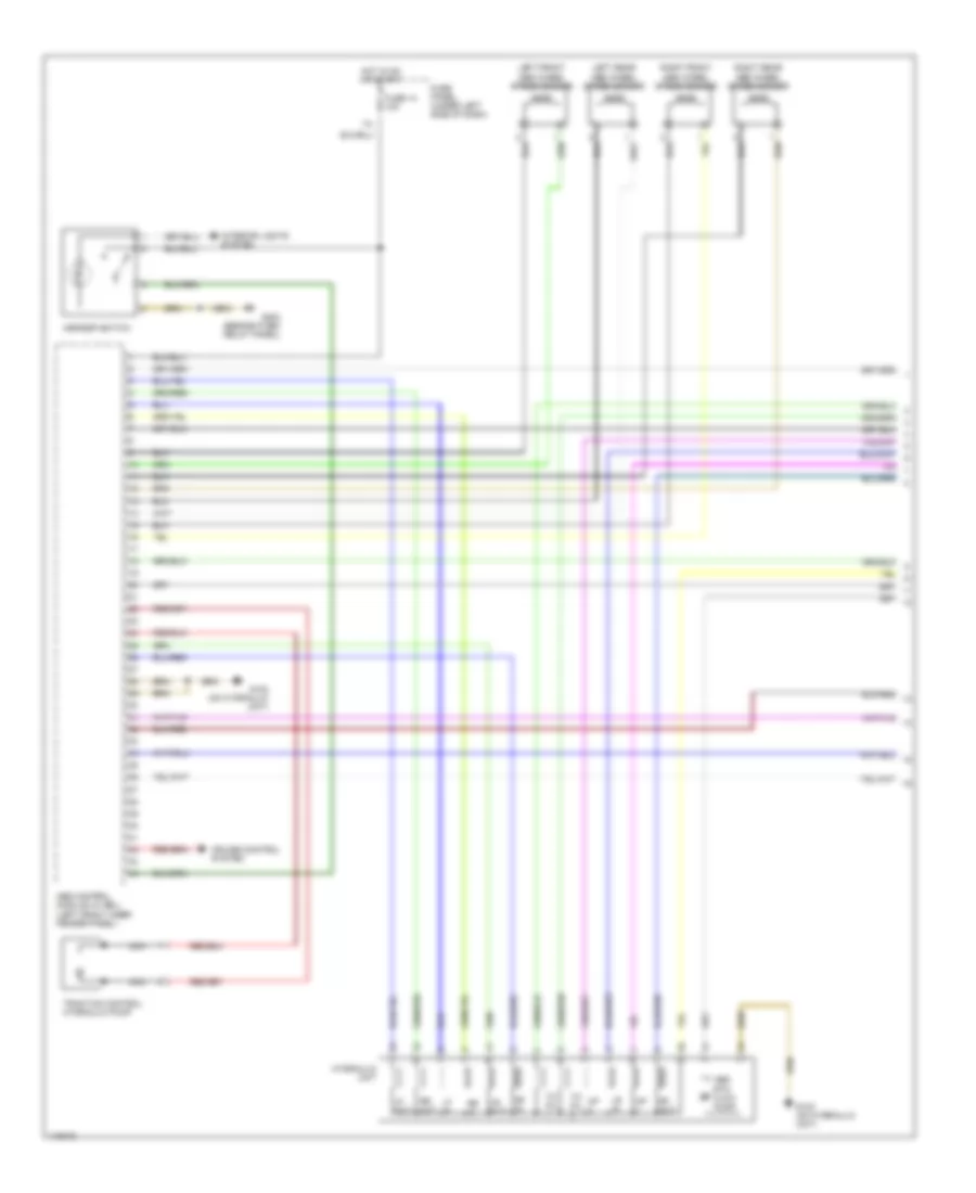
Anti-lock Brake Wiring Diagrams, Late Production with Traction Control, with 4Motion (1 of 2) for Volkswagen Passat GLS 2001
List of elements for Anti-lock Brake Wiring Diagrams, Late Production with Traction Control, with 4Motion (1 of 2) for Volkswagen Passat GLS 2001:
- Abs control module (w/ edl) (left front inner fender panel)
- Abs rtn flow pump
- Asr/esp switch
- Cruise control system
- Fuse 14 10a
- Fuse panel (under left side of dash)
- G102 (on hydraulic unit)
- G202 (beside fuse/ relay panel)
- Hot in on or start
- Hydraulic unit
- Interior lights system
- Left front abs wheel speed sensor
- Left rear abs wheel speed sensor
- Lf in
- Lf out
- Lr in
- Lr out
- Nca
- Rf in
- Rf out
- Right front abs wheel speed sensor
- Right rear abs wheel speed sensor
- Rr in
- Rr out
- Tc pil
- Traction control hydraulic pump
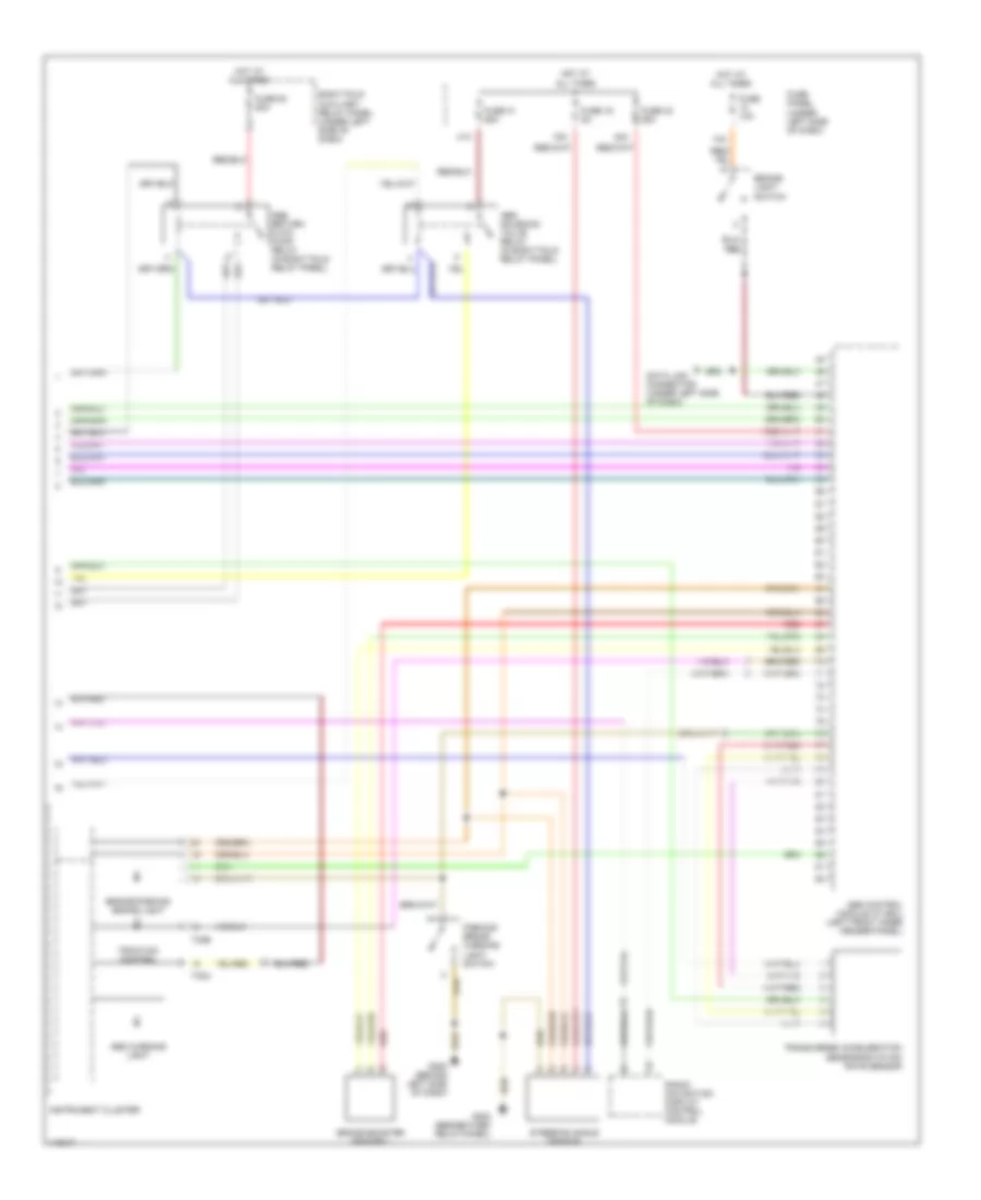
Anti-lock Brake Wiring Diagrams, Late Production with Traction Control, with 4Motion (2 of 2) for Volkswagen Passat GLS 2001
List of elements for Anti-lock Brake Wiring Diagrams, Late Production with Traction Control, with 4Motion (2 of 2) for Volkswagen Passat GLS 2001:
- 13a
- 16a
- 41a
- 42a
- Abs control module (w/ edl) (left front inner fender panel)
- Abs return flow pump relay (in eight fold relay panel)
- Abs solenoid valve relay (in eight fold relay panel)
- Abs warning light
- Brake booster sender 1
- Brake- light switch
- Brake/parking brake light
- Data link connector (under left side of dash)
- Eight fold auxiliary relay panel (under left side of dash)
- Fuse 10a
- Fuse 16 5a
- Fuse 41 25a
- Fuse 42 25a
- Fuse 53 50a
- Fuse panel (under left side of dash)
- G202 (behind left side of dash)
- G202 (beside fuse/ relay panel)
- Hot at all times
- Instrument cluster
- Parking brake warning light switch
- Radio/ navigation display control module
- Red
- Steering angle sensor
- T32a
- T32b
- Traction control
- Transverse acceleration sensor/rotation rate sensor
Anti-lock Brake Wiring Diagrams, Late Production with Traction Control, with FWD for Volkswagen Passat GLS 2001
List of elements for Anti-lock Brake Wiring Diagrams, Late Production with Traction Control, with FWD for Volkswagen Passat GLS 2001:
- 13a
- Abs control module (left front inner fender panel)
- Abs return flow pump
- Abs return flow pump relay
- Abs solenoid valve relay
- Abs warning ind
- Anti-slip control switch
- Brake pad wear sensor indicator
- Brakelight switch (below left side of dash)
- Computer data lines system
- Control module with indicator unit
- Data link connector (under left side of dash)
- Fuse 10a
- Fuse 50a
- Fuse panel (under left side of dash)
- G102 (on hydraulic unit)
- G103 (right side of engine compt)
- G202 (beside fuse/ relay panel)
- Hot at all times
- Hot in on & start
- Instrument cluster
- Interior lights system
- Left front abs inlet valve
- Left front abs outlet valve
- Left front abs wheel speed sensor (on front of left front wheel bearing assembly)
- Left front brake pad wear sensor
- Left front traction control outlet valve
- Left front traction control switch-over valve
- Left rear abs inlet valve
- Left rear abs outlet valve
- Left rear abs wheel speed sensor (on back of left rear wheel bearing assembly)
- Radio/ navigation display control module
- Right front abs inlet valve
- Right front abs outlet valve
- Right front abs wheel speed sensor (on front of right front wheel bearing assembly)
- Right front brake pad wear sensor
- Right front traction control outlet valve
- Right front traction control switch-over valve
- Right rear abs inlet valve
- Right rear abs outlet valve
- Right rear abs wheel speed sensor (on back of right rear wheel bearing assembly)
- T16
- T32a
- T32b
- Thirteen fold auxiliary relay panel (under left side of dash)
- Traction control ind
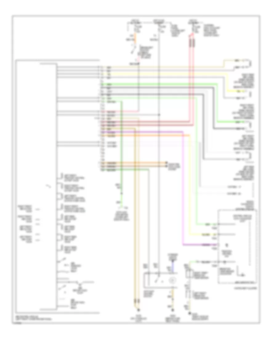
Anti-lock Brake Wiring Diagrams, Late Production without Traction Control for Volkswagen Passat GLS 2001
List of elements for Anti-lock Brake Wiring Diagrams, Late Production without Traction Control for Volkswagen Passat GLS 2001:
- 13a
- 4 motion
- Abs control module (left front inner fender panel)
- Abs return flow pump
- Abs return flow pump relay
- Abs solenoid valve relay
- Abs warning ind
- Brake pad wear sensor indicator
- Brakelight switch (below left side of dash)
- Control module with indicator unit
- Data link connector (under left side of dash)
- Fuse 10a
- Fuse 50a
- Fuse panel (under left side of dash)
- Fwd
- G102 (on hydraulic unit)
- G103 (right side of engine compt)
- Hot at all times
- Hot in on & start
- Instrument cluster
- Left front abs inlet valve
- Left front abs outlet valve
- Left front abs wheel speed sensor (on front of left front wheel bearing assembly)
- Left front brake pad wear sensor
- Left front traction control outlet valve
- Left front traction control switch-over valve
- Left rear abs inlet valve
- Left rear abs outlet valve
- Left rear abs wheel speed sensor (on back of left rear wheel bearing assembly)
- Motronic engine control module (left rear corner of engine compt)
- Radio/ navigation display control module
- Right front abs inlet valve
- Right front abs outlet valve
- Right front abs wheel speed sensor (on front of right front wheel bearing assembly)
- Right front brake pad wear sensor
- Right front traction control outlet valve
- Right front traction control switch-over valve
- Right rear abs inlet valve
- Right rear abs outlet valve
- Right rear abs wheel speed sensor (on back of right rear wheel bearing assembly)
- T16
- T32a
- T32b
- Thirteen fold auxiliary relay panel (under left side of dash)