ANTI-LOCK BRAKES
Anti-lock Brakes Wiring Diagram (1 of 2) for Volkswagen Passat VR6 4Motion 2008

List of elements for Anti-lock Brakes Wiring Diagram (1 of 2) for Volkswagen Passat VR6 4Motion 2008:
- (behind right side of dash) comfort system central control module
- (in brake fluid master cylinder fluid reservoir)
- (right rear of engine compt) abs control module
- 17a
- Abs hydraulic pump
- Abs return flow pump
- Abs warning lamp ind
- Asr/esp control lamp
- Brake booster vacuum sensor (if equipped)
- Brake fluid level warning switch
- Brake system warning lamp ind
- Computer data lines system
- Electro-mechanical parking brake control module (under center console)
- Fuse 30a
- Fuse 40a
- Fuse 5a
- Fuse panel a (left side of engine compt)
- Fuse panel b (left side of engine compt)
- Fuse panel d (at right end of dash)
- G13 (right rear of engine compt)
- G639 (at left "a" pillar)
- G639 (on left "a" pillar)
- Hot at all times
- Instrument cluster
- Left front abs inlet valve
- Left front abs outlet valve
- Left front brake pad wear sensor
- Left front electronic differential lock (edl) outlet valve
- Left rear abs inlet valve
- Left rear abs outlet valve
- Red
- Right front abs inlet valve
- Right front abs outlet valve
- Right front electronic differential lock (edl) switch-over valve
- Right rear abs inlet valve
- Right rear abs outlet valve
- T40
- T6an
- W/ electronics box high
- W/ electronics box low
- Warning systems
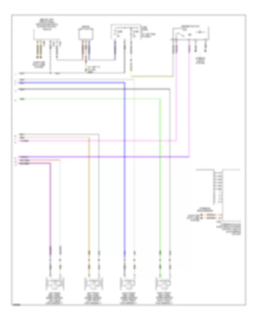
Anti-lock Brakes Wiring Diagram (2 of 2) for Volkswagen Passat VR6 4Motion 2008
List of elements for Anti-lock Brakes Wiring Diagram (2 of 2) for Volkswagen Passat VR6 4Motion 2008:
- (at left "a" pillar) g639
- (behind left side of dash) vehicle electrical system control module
- Asr/esp switch
- Brake light switch
- Computer data lines system
- Fuse 5a
- Fuse panel c (at left end of dash)
- Hub assembly)
- Interior lights system
- Left front abs wheel speed sensor (left front hub assembly)
- Left rear abs wheel speed sensor (left rear hub assembly)
- Right front abs wheel speed sensor (right front
- Right rear abs wheel speed sensor (right rear hub assembly)
- Steering angle sensor
- Steering column electronic systems control module (on steering column)
- T12m
- T16g
- T20d
- T2cq