ANTI-LOCK BRAKES
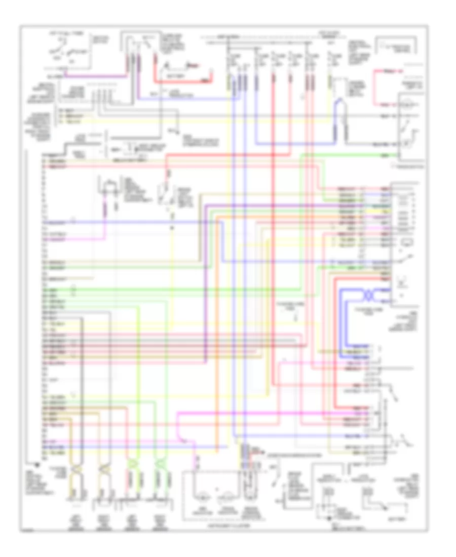
Anti-lock Brake Wiring Diagrams for Volvo 850 GLT 1995
List of elements for Anti-lock Brake Wiring Diagrams for Volvo 850 GLT 1995:
- (below battery)
- (on brake fluid reservoir)
- A13
- A18
- A28
- A29
- Abs combination relay (left rear of engine compt)
- Abs control module (left rear of engine compartment)
- Abs hydraulic unit (left front engine compt)
- Abs indicator
- Abs pedal sensor (left rear of engine compartment)
- Acc
- Battery
- Body ground connector
- Brake fluid level sensor
- Brake light switch (below left i/p)
- Brake warning indicator
- Central electrical unit (left rear of engine compt)
- Control
- Early prod
- Early production
- Fuse 10a
- Fuse 15a
- Fuse 30a
- G111
- G111 (below battery)
- G205 (top right side of steering column)
- Hazard/ flasher relay switch
- Hot at all times
- Hot in acc or run
- Hot in run
- Ignition switch
- Instrument cluster
- Late prod
- Late production
- Left front abs sensor
- Left rear abs sensor
- Nca
- Off
- On-board diagnostic connector a (partial) (right front of engine compt)
- Overload relay #2 (in central electrical unit)
- Pnk
- Power ground connector
- Red
- Rheostat (left i/p)
- Right front abs sensor
- Right rear abs sensor
- Start
- Starting/charging system
- Tracs indicator
- Tracs switch
- Twisted wire pair
- Twisted wire pairs
- W/ traction
 English