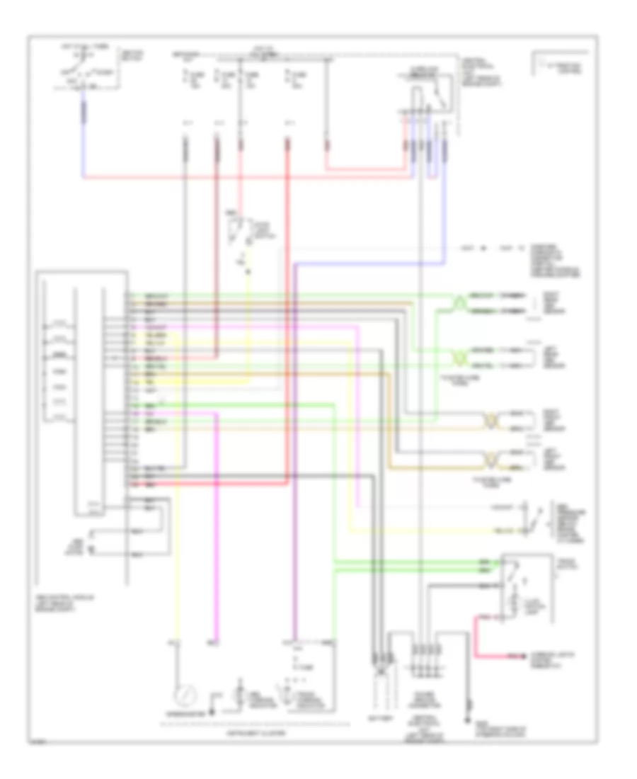
ANTI-LOCK BRAKES
Anti-lock Brake Wiring Diagrams for Volvo 850 GLT 1996
List of elements for Anti-lock Brake Wiring Diagrams for Volvo 850 GLT 1996:
- A18
- A29
- Abs control module (left rear of engine compt)
- Abs pump motor
- Abs warning indicator
- Acc
- Battery
- Central electrical unit (left rear of engine compt)
- Control
- Ebd pressure sensor (below brake master cylinder)
- Fuse
- Fuse 10a
- Fuse 15a
- Fuse 30a
- G205 (top right side of steering column)
- Hot at all times
- Hot in on
- Ignition switch
- Illum- ination lamp
- Instrument cluster
- Interior lights system (rheostat)
- Left front abs sensor
- Left rear abs sensor
- M (+)
- M (-)
- Nca
- Off
- On-board diagnostic connector (partial) (center console, forward shifter)
- Overload relay #2
- Pnk
- Power ground connector
- Red
- Right front abs sensor
- Right rear abs sensor
- Speedometer
- Start
- Stop light switch
- Tracs switch
- Tracs warning indicator
- Twisted wire pairs
- W/ traction
 English