ANTI-LOCK BRAKES
Anti-lock Brakes Wiring Diagram, with Dynamic Stability Control for Volvo C30 T-5 2012

List of elements for Anti-lock Brakes Wiring Diagram, with Dynamic Stability Control for Volvo C30 T-5 2012:
- 64/113
- 64/816
- 64/817
- Body sensor cluster stability sensor (bsc) (under front passenger's seat)
- Brake control module (bcm) (at left rear corner of engine compt)
- Brake pedal sensor (at left rear corner of engine compt)
- Central electronic module (behind right side of dash)
- Computer data lines system
- Engine compartment distribution box (left side of engine compt)
- Fuse f52 5a
- Fuse f7 30a
- Fuse f8 20a
- G119 (on left front strut tower)
- G80 (on left front strut tower)
- Hot at all times
- Hot in run or start
- Left front abs sensor (at left front wheel, on spindle/hub assembly)
- Left rear abs sensor (at left rear wheel, on spindle/hub assembly)
- Red
- Right front abs sensor (at right front wheel, on spindle/hub assembly)
- Right rear abs sensor (at right rear wheel, on spindle/hub assembly)
- Steering wheel module (swm) (top of steering column)
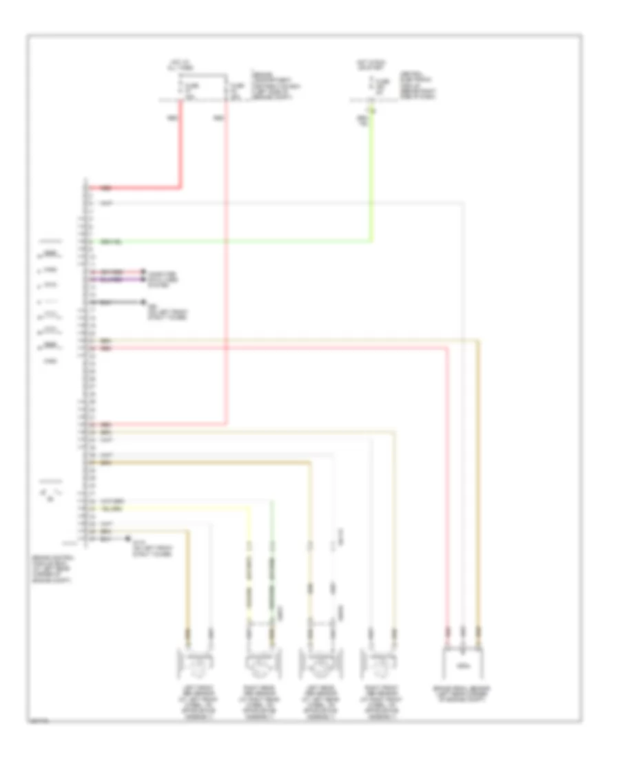
Anti-lock Brakes Wiring Diagram, without Dynamic Stability Control for Volvo C30 T-5 2012
List of elements for Anti-lock Brakes Wiring Diagram, without Dynamic Stability Control for Volvo C30 T-5 2012:
- 64/113
- 64/816
- 64/817
- Brake control module (bcm) (at left rear corner of engine compt)
- Brake pedal sensor (left rear corner of engine compt)
- Central electronic module (behind right side of dash)
- Computer data lines system
- Engine compartment distribution box (left side of engine compt)
- Fuse f52 5a
- Fuse f7 30a
- Fuse f8 20a
- G119 (on left front strut tower)
- G80 (on left front strut tower)
- Hot at all times
- Hot in run or start
- Left front abs sensor (at left front wheel, on spindle/hub assembly)
- Left rear abs sensor (at left rear wheel, on spindle/hub assembly)
- Red
- Right front abs sensor (at right front wheel, on spindle/hub assembly)
- Right rear abs sensor (at right rear wheel, on spindle/hub assembly)