ANTI-LOCK BRAKES
Anti-lock Brake Wiring Diagrams, with AWD for Volvo S60 2002

List of elements for Anti-lock Brake Wiring Diagrams, with AWD for Volvo S60 2002:
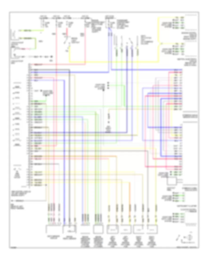
Anti-lock Brake Wiring Diagrams, with Dynamic Stability Control for Volvo S60 2002
List of elements for Anti-lock Brake Wiring Diagrams, with Dynamic Stability Control for Volvo S60 2002:
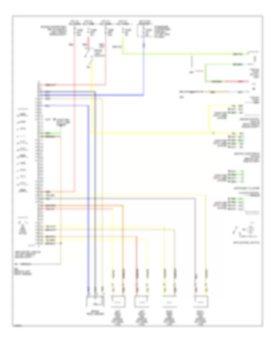
Anti-lock Brake Wiring Diagrams, without Dynamic Stability Control for Volvo S60 2002
List of elements for Anti-lock Brake Wiring Diagrams, without Dynamic Stability Control for Volvo S60 2002: