ANTI-LOCK BRAKES
Anti-lock Brakes Wiring Diagram, with Dynamic Stability Control for Volvo S60 T-5 2008

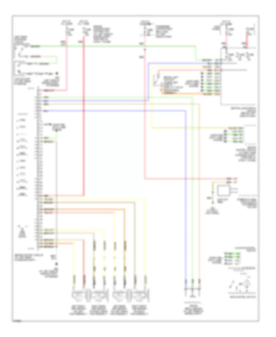
List of elements for Anti-lock Brakes Wiring Diagram, with Dynamic Stability Control for Volvo S60 T-5 2008:
- (at brake master cylinder) dstc activation module
- (left rear of engine) vacuum pump switch
- A10
- A11
- A37
- A55
- Abs pump motor
- B11
- B13
- B22
- B26
- Body sensor cluster stability sensor (bsc) (under front passenger's seat)
- Brake control module (at left rear of engine compt)
- Brake light contact (under left side of dash, at top of brake pedal assembly)
- Brake pedal sensor (at left rear of engine compt)
- Brake pressure sensor 1 (on brake master cylinder)
- Brake pressure sensor 2 (on brake master cylinder)
- C21
- C22
- C34
- C35
- Central electronic module (behind left side of dash)
- Climate control module
- Computer data lines system
- Contact reel
- D31
- D32
- D34
- D46
- D47
- D49
- Engine compartment distribution (at left side of engine compt, forward of strut tower)
- Engine control module (at right side of engine compt, forward of strut tower)
- Fuse 20a
- Fuse 50a
- Fuse 5a
- Fuse b1 30a
- Fuse b2 30a
- Fuse c9 5a
- G84 (at right kick panel)
- G93 (left side of engine compt, on fender)
- G95 (at left side of engine compt, on fender)
- Hot at all times
- Left front abs sensor (on left hub assembly)
- Left rear abs sensor (on left rear hub assembly)
- Main fuses
- Nca
- Passenger compartment relay box (behind left side of dash)
- Red
- Right front abs sensor (on right hub assembly)
- Right rear abs sensor (on right rear hub assembly)
- Spin control switch
- Steering angle sensor module
- Steering wheel module (swm) (in steering column)
- Vacuum pump (at left rear of engine)
Anti-lock Brakes Wiring Diagram, without Dynamic Stability Control for Volvo S60 T-5 2008
List of elements for Anti-lock Brakes Wiring Diagram, without Dynamic Stability Control for Volvo S60 T-5 2008:
- (left rear of engine) vacuum pump switch
- A10
- A11
- A37
- A55
- Abs pump motor
- B11
- B13
- B22
- B26
- Brake control module (at left rear of engine compt)
- Brake light contact (under left side of dash, at top of brake pedal assembly)
- Brake pedal sensor (at left rear of engine compt)
- C21
- C22
- C34
- C35
- Central electronic module (behind left side of dash)
- Climate control module
- Computer data lines system
- Contact reel
- D32
- D34
- D47
- D49
- Engine compartment distribution (at left side of engine compt, forward of strut tower)
- Engine control module (at right side of engine compt, forward of strut tower)
- Fuse 20a
- Fuse 50a
- Fuse 5a
- Fuse b1 30a
- Fuse b2 30a
- Fuse c9 5a
- G84 (at right kick panel)
- G93 (left side of engine compt, on fender)
- G95 (at left side of engine compt, on fender)
- Hot at all times
- Left front abs sensor (on left hub assembly)
- Left rear abs sensor (on left rear hub assembly)
- Main fuses
- Nca
- Passenger compartment relay box (at left side of dash)
- Red
- Right front abs sensor (on right hub assembly)
- Right rear abs sensor (on right rear hub assembly)
- Spin control switch
- Steering wheel module (swm) (in steering column)
- Vacuum pump (at left rear of engine)