ANTI-LOCK BRAKES
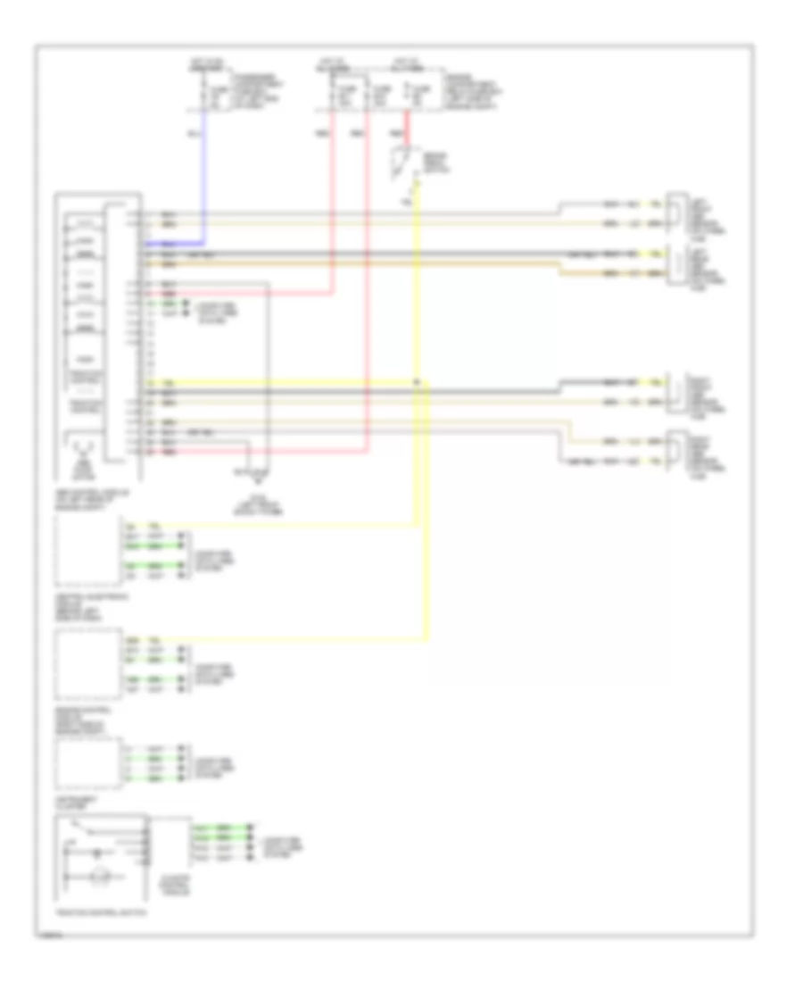
Anti-lock Brake Wiring Diagrams for Volvo S80 T-6 1999
List of elements for Anti-lock Brake Wiring Diagrams for Volvo S80 T-6 1999:
- A11
- A12
- A13
- A14
- A37
- A55
- Abs control module (on left rear of engine compt)
- Abs pump motor
- B13
- B17
- B18
- B26
- Brake pedal switch
- Central electronic module (behind left side of dash)
- Climate control module
- Computer data lines system
- Engine compartment relay/fuse box (left side of engine compt)
- Engine control module (right side of engine compt)
- Fuse b11 30a
- Fuse b12 30a
- Fuse b3 5a
- Fuse c9 5a
- G102 (left front shock tower)
- Hot at all times
- Hot in on or start
- Instrument cluster
- Left front abs sensor (on wheel hub)
- Left rear abs sensor (on wheel hub)
- Passenger compartment fuse box (at left end of dash)
- Red
- Right front abs sensor (on wheel hub)
- Right rear abs sensor (on wheel hub)
- Traction control
- Tracton control switch
 English